Portable electronic device

Active Publication Date: 2008-07-31
INVENTEC CORP
View PDF5 Cites 2 Cited by
  • Summary
  • Abstract
  • Description
  • Claims
  • Application Information

AI Technical Summary

Benefits of technology

[0006]In view of the above, the object of the present invention is to provide a portable electronic device for improving output sound quality of a speaker thereof and improving the input / output interface to meet the requirements of different operating modes.
[0007]To achieve the above object, a portable electronic device of the present invention is provided, which includes a first body, a second body, and at least one speaker. The second body is pivotally connected to a side edge of the first body, such that the second body is selectively rotated to cover the first body, or to form an angle with respect to the first body. The speaker is movably disposed on an upper surface of the first body to be moved relative to the first body. Thus, the speaker can be moved and fixed to a predetermined position on the first body to achieve optimized output sound quality.
[0009]The present invention provides different operating and display configurations in different operating modes, such that a user can obtain optimized operating and display configurations in different operating modes. Besides, the speaker can be fixed at an optimal position to achieve optimized output sound quality.

Problems solved by technology

Since the volume of the portable electronic devices is relatively small, there is no sufficient space in speakers currently used in portable electronic devices for sound resonance, the portable electronic devices have a small sound output power and poor output sound quality.
Moreover, as a speaker is usually fixed at a certain position, the relative position between the speaker and the main body of a portable electronic device cannot be changed.
Thus, the relative position of the speaker cannot satisfy the optimization requirement in different operating modes.
However, the portable external speaker is an extra kit for a user, thus causing inconvenience.
However, the input / output interface of the portable electronic device cannot meet the requirements of different application modes at the same time, such that how to improve the design of the input / output interface has become a subject of the portable electronic device to be solved.

Method used


Image

  • Portable electronic device
  • Portable electronic device
  • Portable electronic device

Examples


Embodiment Construction

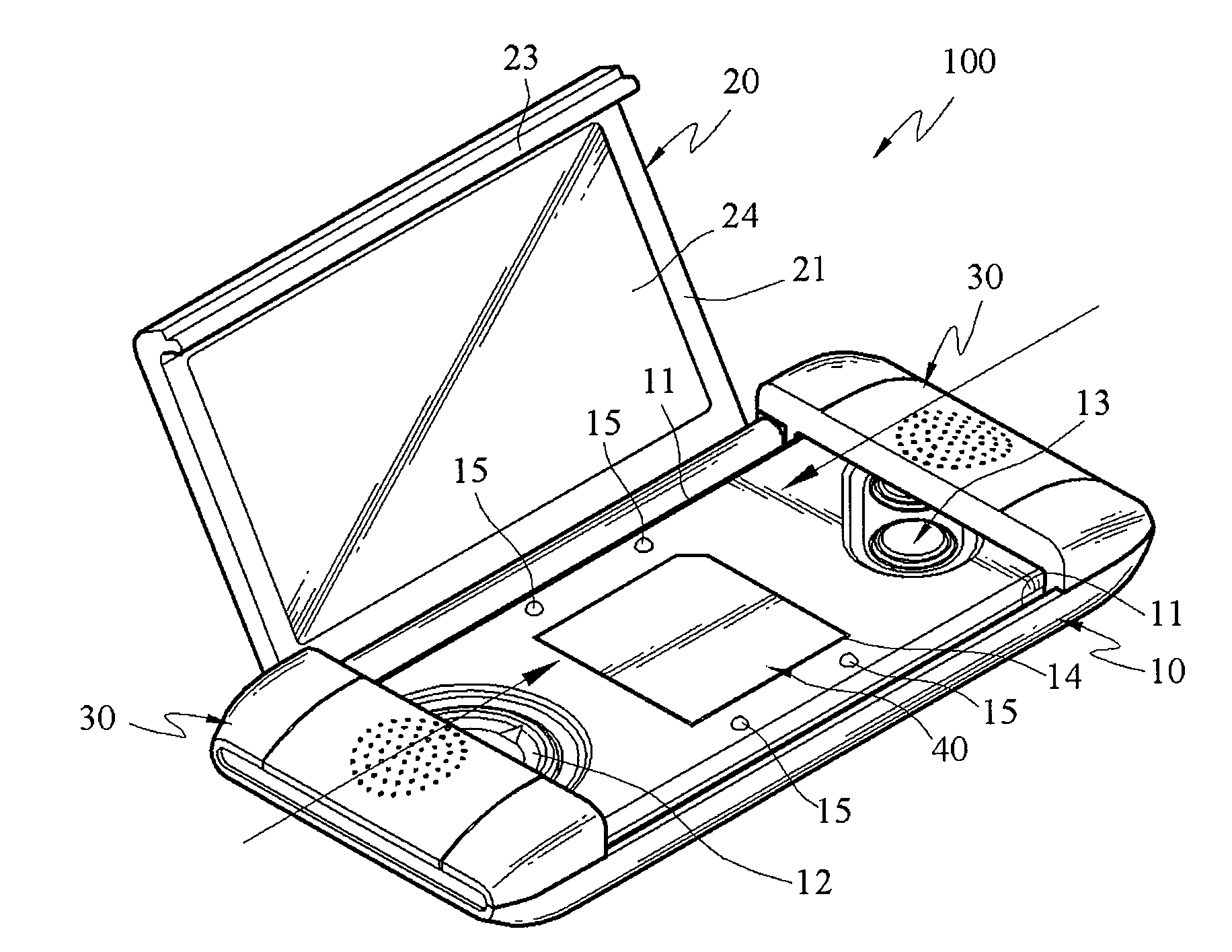
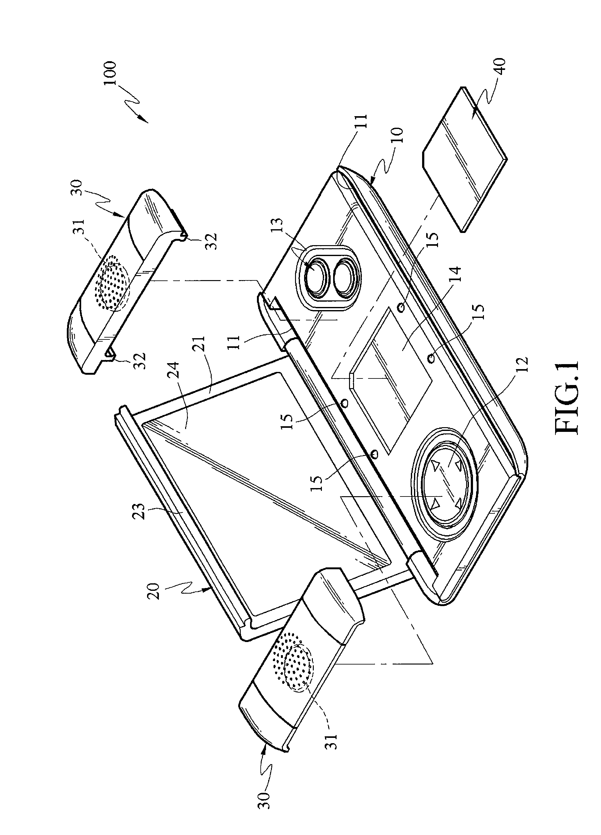
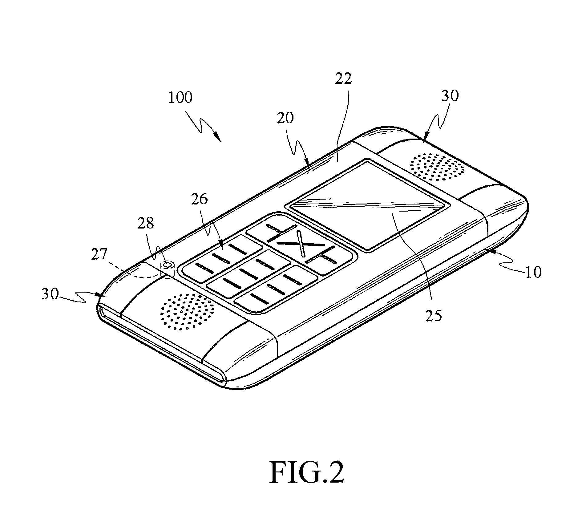
[0021]Referring to FIGS. 1, 2, and 3, a portable electronic device 100 of an embodiment of the present invention is provided, wherein the portable electronic device 100 includes a first body 10, a second body 20, and two speakers 30.

[0022]A control circuit 10a and a communication module 10b are disposed in the first body 10. The control circuit 10a is provided to receive and process signals. The communication module 10b is electrically connected to the control circuit 10a, wherein the communication module 10b is used to transmit and receive wireless signals through a wireless communication protocol, so as to transmit the signals to the control circuit 10a. Two guiding slots 11 are formed on a upper surface of the first body 10, and the two guiding slots 11 are formed along the two opposite long sides of the upper surface of the first body 10, wherein the width of the opening of each guiding slot 11 is smaller than that of the interior of the guiding slot 11.

[0023]Moreover, a directi...


PUM


Abstract

A portable electronic device including a first body, a second body, and at least one speaker is provided. The second body is pivotally connected to one side edge of the first body, such that the second body is selectively rotated to cover the first body, or to form an angle with respect to the first body. The speaker is movably disposed on an upper surface of the first body, and can be moved relative to the first body. Thus, the speaker can be moved and fixed to a predetermined position to achieve optimized output sound quality.

Description

BACKGROUND OF THE INVENTION[0001]1. Field of Invention[0002]The present invention relates to a portable electronic device, and more particularly to a portable electronic device for achieving optimized output sound quality by moving the speaker to change position.[0003]2. Related Art[0004]The application of multi-media such as films, music, and video games has become the mainstream application for portable electronic devices in the future. Since the volume of the portable electronic devices is relatively small, there is no sufficient space in speakers currently used in portable electronic devices for sound resonance, the portable electronic devices have a small sound output power and poor output sound quality. Moreover, as a speaker is usually fixed at a certain position, the relative position between the speaker and the main body of a portable electronic device cannot be changed. Thus, the relative position of the speaker cannot satisfy the optimization requirement in different oper...

Claims


Application Information

Patent Timeline
IPC IPC(8): H05K7/02
CPCH04M1/0216H04M1/0247H04M1/03H04R2499/15H04R2205/024H04R2499/11H04R5/02
Inventor WANG, SHIH-HSUANTSAI, PEI-RU
Owner INVENTEC CORP
Why Eureka
Try Eureka