
a compression limiter

A compression limiting and compression control technology, applied in the direction of limiting amplitude, electrical components, amplification control, etc., can solve the problems of easily damaged speakers, poor hearing of equipment, etc., and achieve the effect of improving output sound quality and improving user experience

Inactive Publication Date: 2019-02-01
WILL SEMICON (SHANGHAI) CO LTD
View PDF5 Cites 0 Cited by
  • Summary
  • Abstract
  • Description
  • Claims
  • Application Information

AI Technical Summary

Problems solved by technology

When clipping and truncation occurs in the system, a large number of harmonic distortion signals will be generated, resulting in poor hearing of the equipment and easy damage to the speaker

Method used

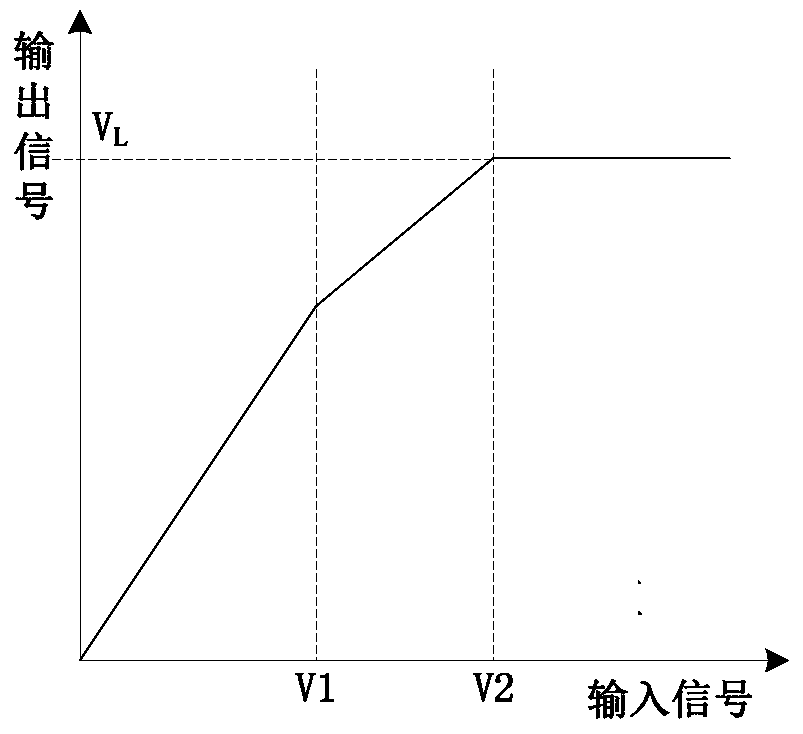
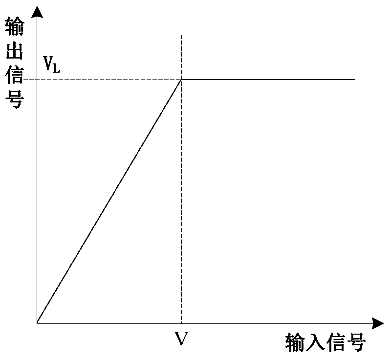
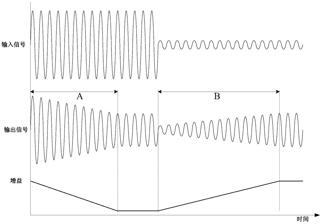

Image

  • a compression limiter
  • a compression limiter
  • a compression limiter

Examples


Embodiment Construction

[0055] In order to more clearly describe the embodiments of the present invention or the technical solutions in the prior art, the specific embodiments of the present invention will be described below with reference to the accompanying drawings. Obviously, the accompanying drawings in the following description are only some embodiments of the present invention. For those of ordinary skill in the art, other drawings can also be obtained from these drawings without creative efforts, and obtain other implementations.

[0056] like Figure 4 Shown is a schematic structural diagram of the first embodiment of the compression limiter 100 provided by the present invention. As can be seen from the figure, the compression limiter 100 includes: a gain adjustment module 110, a loudspeaker module 120 and a clipping control Module 130 , wherein the amplification module 120 is connected to the gain adjustment module 110 , and the clipping control module 130 is connected to the amplification...


PUM


Abstract

The invention provides a compression limiter, comprising a gain adjusting module, which outputs first output signals according to input signals of the compression limiter, and in accordance with the first output signal, carries out feedback regulation of first signal gains used for realizing signal compression limiting; a sound amplification module, which is connected with the gain adjusting module to carry out power amplification of the first output signals outputted by the gain adjusting module and to output second output signals; and a clipping control module, which is connected with the sound amplification module to carry out feedback regulation of second signal gains used for realizing power amplification of the first output signals according to clipping distortion of the second output signals outputted by the sound amplification module. Under the joint effect of the first signal gains and the second signal gains, the second output signals outputted by the compression limiter are outputted within the amplitude limit. The clipping distortion of the second output signals is automatically eliminated, thereby increasing the output sound quality of the sound amplification module and improving the user experience.

Description

technical field [0001] The invention relates to the technical field of audio processing, in particular to a compression limiter. Background technique [0002] The dynamic range of human hearing can reach 120dB (decibels), and the maximum sound that can be heard is 1 million times larger than the minimum sound. When the amplification device is playing audio signals, it is often limited by the noise floor of the amplification device itself and the maximum output capability (dynamic range of the device) of the amplification device. For example, smaller sounds will be submerged in the noise floor of the system. The loudest sound is limited by the maximum output capability of the amplification equipment, and even clipping distortion occurs. In order to solve this problem, the dynamic processing of sound signals is introduced, which reduces the dynamic range of the sound so that the amplifier can play normally, and the compression limiting technology belongs to one of them. [0...

Claims


Application Information

Patent Timeline
Patent Type & Authority Patents(China)
IPC IPC(8): H03G11/00
Inventor 张振浩徐剑尹辉
Owner WILL SEMICON (SHANGHAI) CO LTD
Learn More