Cabinet Lamp

a technology for cabinet lamps and lampshades, which is applied in the field of cabinet lamps, can solve the problems of easily bumped and damaged, interfere with the storage space available, and achieve the effect of maximizing the light outpu

Inactive Publication Date: 2008-07-31
HANSEN DAVID B
View PDF21 Cites 2 Cited by
  • Summary
  • Abstract
  • Description
  • Claims
  • Application Information

AI Technical Summary

Benefits of technology

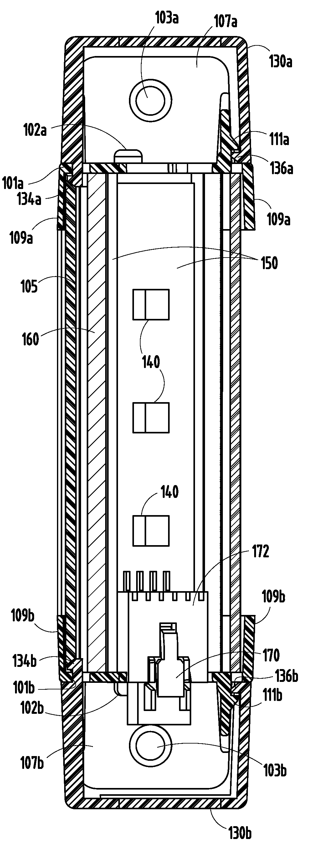
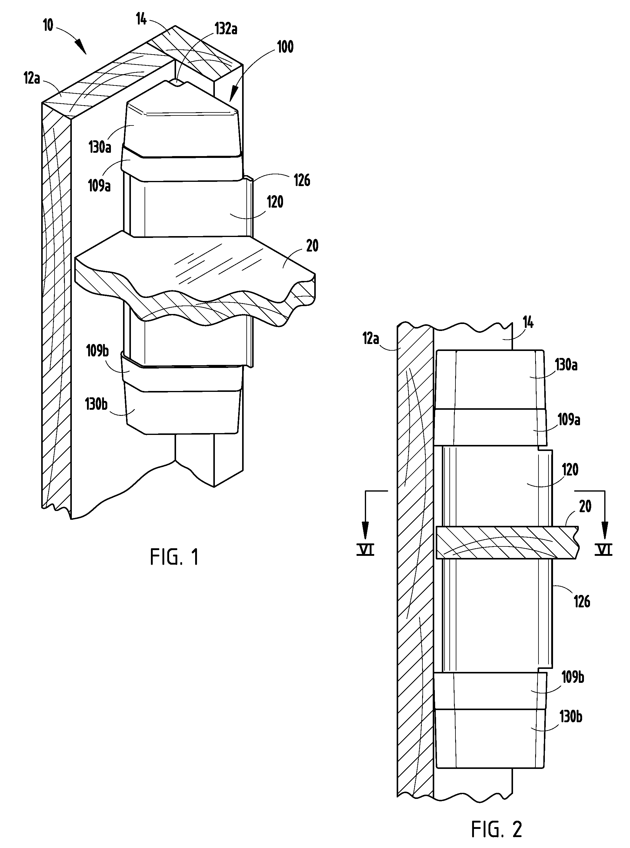
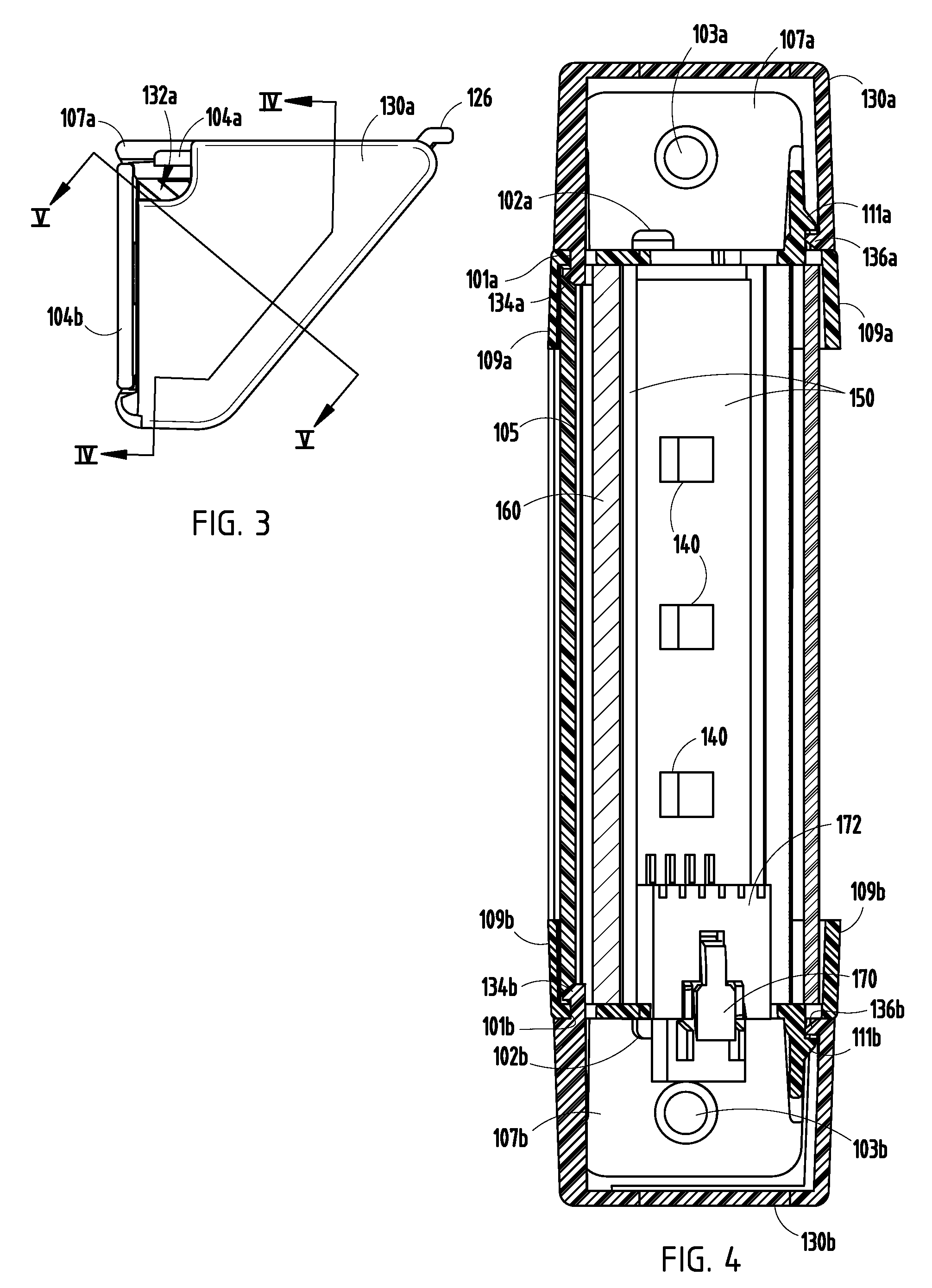
[0005]The system of the present invention provides this advantage by providing an elongated cabinet light having walls which are joined at an edge which may engage a corner of the cabinet. Illumination means is positioned within the walls defining the lamp housing and a light transmissive cover is placed across the free ends of the walls and has at least one portion that is diagonal relative to the walls to maximize the light output.

Problems solved by technology

Such fixtures, although providing interior illumination for a cabinet, frequently interfere with the storage space available in the cabinet and can be easily bumped and damaged while placing items within a cabinet.

Method used


Image

  • Cabinet Lamp
  • Cabinet Lamp
  • Cabinet Lamp

Examples


Embodiment Construction

[0025]Reference will now be made in detail to the present preferred embodiments of the invention, examples of which are illustrated in the accompanying drawings. Wherever possible, the same reference numerals will be used throughout the drawings to refer to the same or like parts.

[0026]For purposes of description herein, the terms “upper,”“lower,”“right,”“left,”“rear,”“front,”“vertical,”“horizontal,”“top,”“bottom,” and derivatives thereof shall relate to the invention as shown in the drawings. However, it is to be understood that the invention may assume various alternative orientations, except where expressly specified to the contrary. It is also to be understood that the specific devices illustrated in the attached drawings and described in the following specification are simply exemplary embodiments of the inventive concepts defined in the appended claims. Hence, specific dimensions, proportions, and other physical characteristics relating to the embodiment disclosed herein are n...


PUM


Abstract

The system of the present invention provides this advantage by providing an elongated cabinet light having walls which are joined at an edge which engages a corner, shelf, top surface, side surface, or bottom surface of the cabinet. An illumination source is positioned within the walls defining the lamp housing and a light transmissive cover is placed across the free ends of the walls with a portion thereof provided diagonally to maximize the light output. The light can be mounted in the inside corner of the front of a cabinet adjacent the door. The light may include a lens extrusion flange which prevents viewing the cut edge of a cabinet shelf when the lamp unit extends between one or more shelves of the cabinet.

Description

CROSS REFERENCE TO RELATED APPLICATION[0001]This application claims priority under 35 U.S.C. §119(e) to U.S. Provisional Application No. 60 / 887,447, filed on Jan. 31, 2007, the entire disclosure of which is incorporated herein by reference.BACKGROUND OF THE INVENTION[0002]The present invention relates to a cabinet lamp and one which is adapted for mounting in the corner of a cabinet.[0003]There exists a variety of aftermarket light fixtures that can be employed for the illumination of a cabinet. Such fixtures include flat, elongated fluorescent fixtures, which are typically mounted to the undersurface of a top shelf or other shelves of a cabinet to project light downwardly onto a lower shelf. Other aftermarket lighting accessories include lamp modules which mount to the side walls of a cabinet for providing illumination horizontally outwardly from the side wall. Such fixtures, although providing interior illumination for a cabinet, frequently interfere with the storage space availab...

Claims


Application Information

Patent Timeline
Patent Type & Authority Applications(United States)
IPC IPC(8): F21V33/00
CPCA47B97/00F21S8/037F21W2131/301F21V33/0012F21Y2101/02F21V27/02F21Y2115/10
Inventor HANSEN, DAVID B.
Owner HANSEN DAVID B
Why Eureka
Try Eureka