Instrumentation And Method For Implanting A Curved Stem Tibial Tray

a technology of tibial stem and instrument, which is applied in the field of tibial trays, can solve the problems of difficult operation of punch assembly, difficult to implant tibial stem into prepared tibial opening,

Active Publication Date: 2008-07-31
BIOMET MFG CORP
View PDF59 Cites 93 Cited by
  • Summary
  • Abstract
  • Description
  • Claims
  • Application Information

AI Technical Summary

Problems solved by technology

In some instances, it may be difficult to implant the tibial stem into the prepared tibial opening because of potential clearance issues with the distal femur and/or s...

Method used


Image

  • Instrumentation And Method For Implanting A Curved Stem Tibial Tray
  • Instrumentation And Method For Implanting A Curved Stem Tibial Tray
  • Instrumentation And Method For Implanting A Curved Stem Tibial Tray

Examples


Embodiment Construction

[0034]The following description of the embodiment(s) is merely exemplary in nature and is in no way intended to limit the invention, its application, or uses.

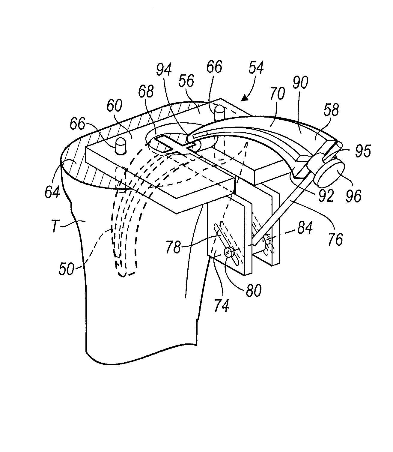
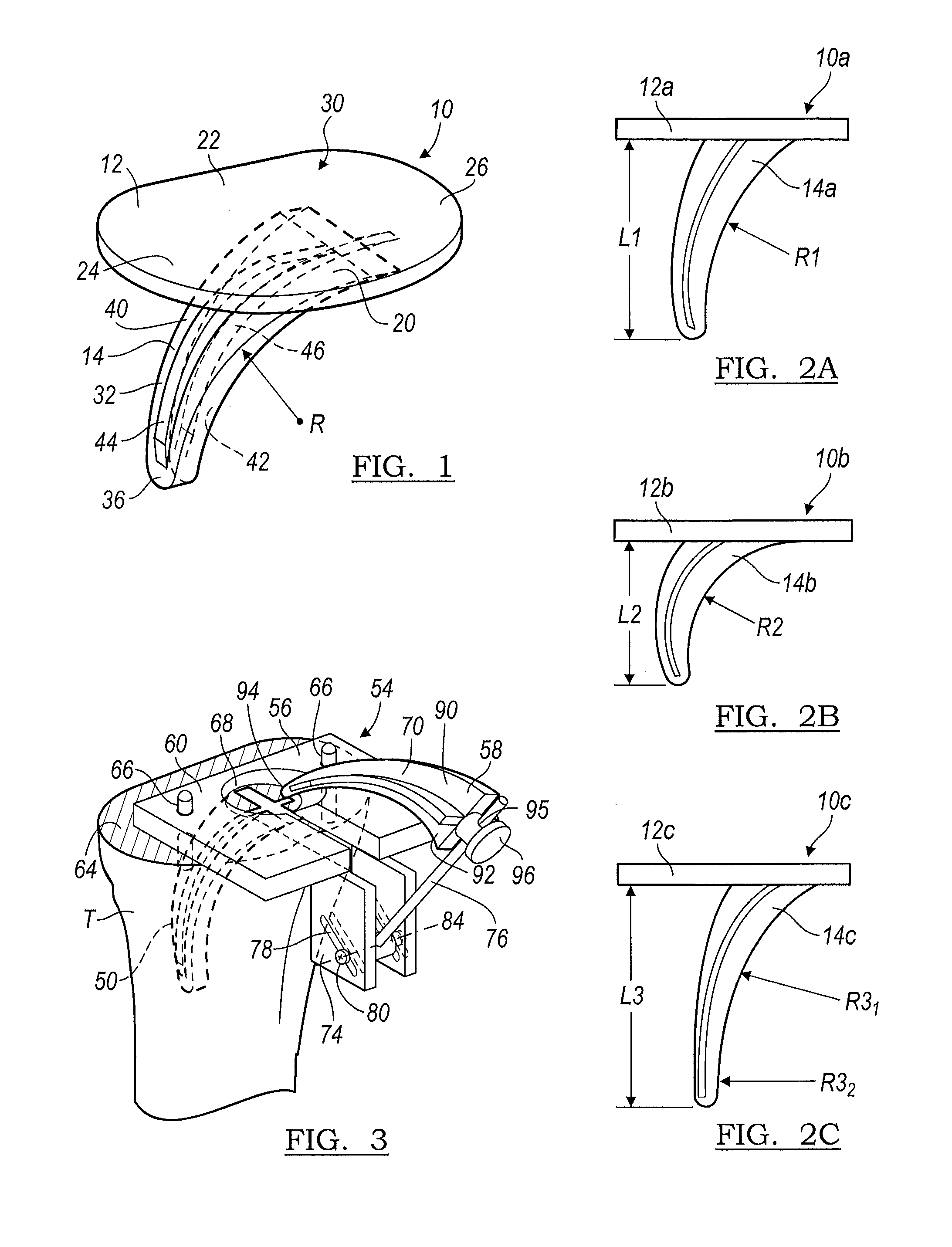
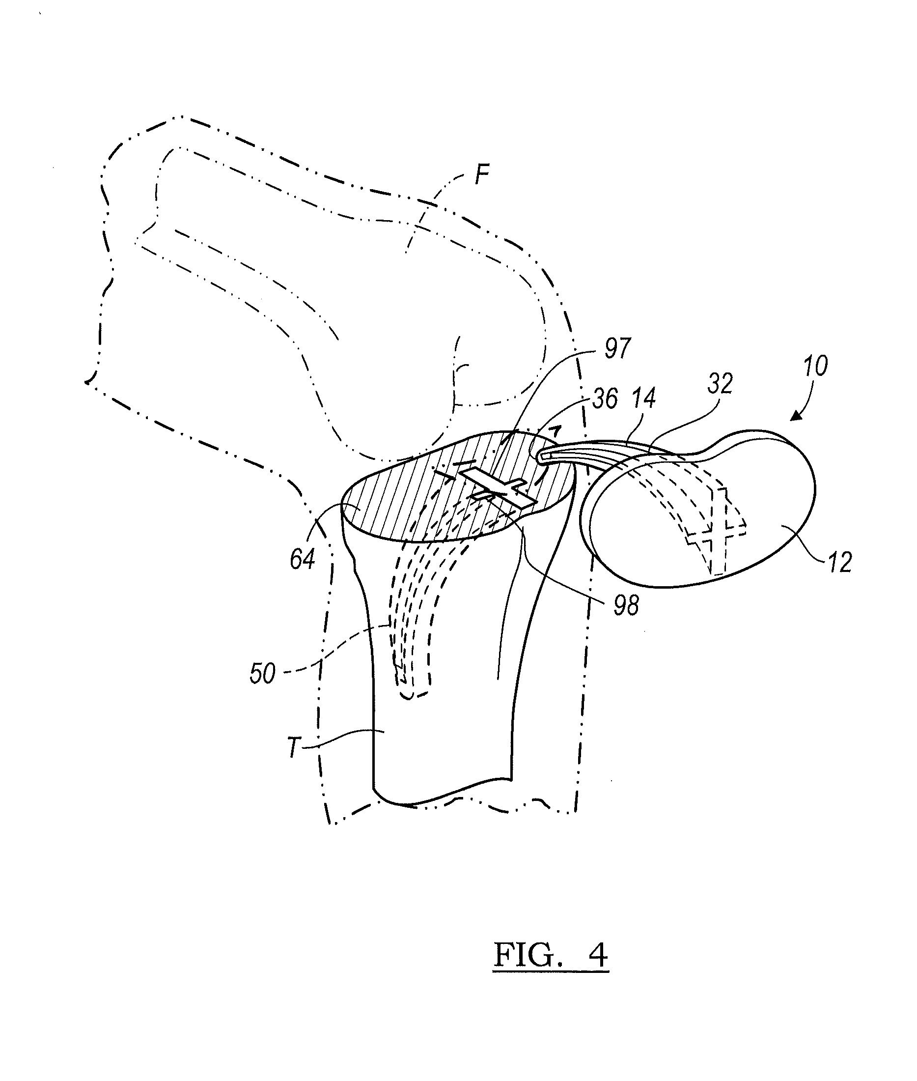
[0035]With initial reference now to FIG. 1 a tibial component 10 is shown. The tibial component 10 generally includes a substantially planar platform-like tray 12 having a fixed, inferiorly extending tibial stem 14. The tibial stem 14 is adapted to be received in a corresponding opening made by a surgeon in the proximal tibia. As will become appreciated from the following discussion, the stem arrangement facilitates a minimally invasive implantation procedure.

[0036]For discussion purposes, the tibial component 10 will be described for use with a knee joint having a surgically resected left tibia. It is understood however that the tibial component 10 may be universal such that it may be adapted for use with a surgically resected right tibia. Likewise, the tibial component 10 may be adapted for use in either a left or right tibia...


PUM


Abstract

A punch assembly for preparing a tibia bone for a prosthesis includes a static component configured to be supported by the tibia bone and a dynamic component that includes a punch having a stem. The dynamic component is supported for movement relative to the static component along a generally arcuate path to prepare an aperture having an arcuate contour in the tibia bone. A method of preparing a tibial aperture for is also disclosed.

Description

CROSS REFERENCE TO RELATED APPLICATION(S)[0001]This application is a continuation-in-part of U.S. patent application Ser. No. 11 / 149,495, filed on Jun. 9, 2005, the disclosure of which is incorporated herein by reference in its entirety.FIELD[0002]This invention relates to tibial trays and more particularly to instrumentation and a method for implementing a curved stem tibial tray.INTRODUCTION[0003]The knee joint is a complex articulating structure. The knee joint includes a femur, which articulates with a tibia, and a patella, which acts as a protective shield for the articulating knee joint. The knee joint also includes soft tissue ligaments that extend on the medial and lateral side of the knee joint, and are generally referred to as collateral ligaments. The soft tissue ligaments which cross within the knee joint are generally referred to as an anterior cruciate ligament and a posterior cruciate ligament.[0004]A knee joint prosthesis typically comprises a femoral component and a...

Claims


Application Information

Patent Timeline
IPC IPC(8): A61B17/58
CPCA61B17/1604A61F2/389A61B17/1764A61B17/1675
Inventor FOX, DUKE, A.METZGER, ROBERTHOEPPNER, JACY C.DETLEFSEN, RICHARD
Owner BIOMET MFG CORP
Why Eureka
Try Eureka