Multi-Part Heat Exchanger

Inactive Publication Date: 2008-08-07
CARRIER COMML REFRIGERATI
View PDF19 Cites 56 Cited by
  • Summary
  • Abstract
  • Description
  • Claims
  • Application Information

AI Technical Summary

Benefits of technology

[0007]According to the invention, a refrigeration system is provided which includes a compressor for driving a refrigerant along a flow path in at least a first mode of system operation; a first heat exchanger along the flow path downstream of the compressor in the first mode; a second heat exchanger along the flow path upstream of the compressor in the first mode; and an expansion device in the flow path downstream of the first heat exchanger and upstream of the second heat exchanger in the first mode, wherein the first heat exchanger comprises a plurality of heat exchanger components arranged along a flow path of heat e

Problems solved by technology

For these applications, the efficiency of the system is often low in comparison to a system with a properly sized

Method used


Image

  • Multi-Part Heat Exchanger
  • Multi-Part Heat Exchanger
  • Multi-Part Heat Exchanger

Examples


Embodiment Construction

[0012]The invention relates to a vapor compression system of a refrigerator unit and, more particularly, to the arrangement of a heat exchanger in a vapor compression system, preferably in a transcritical vapor compression system.

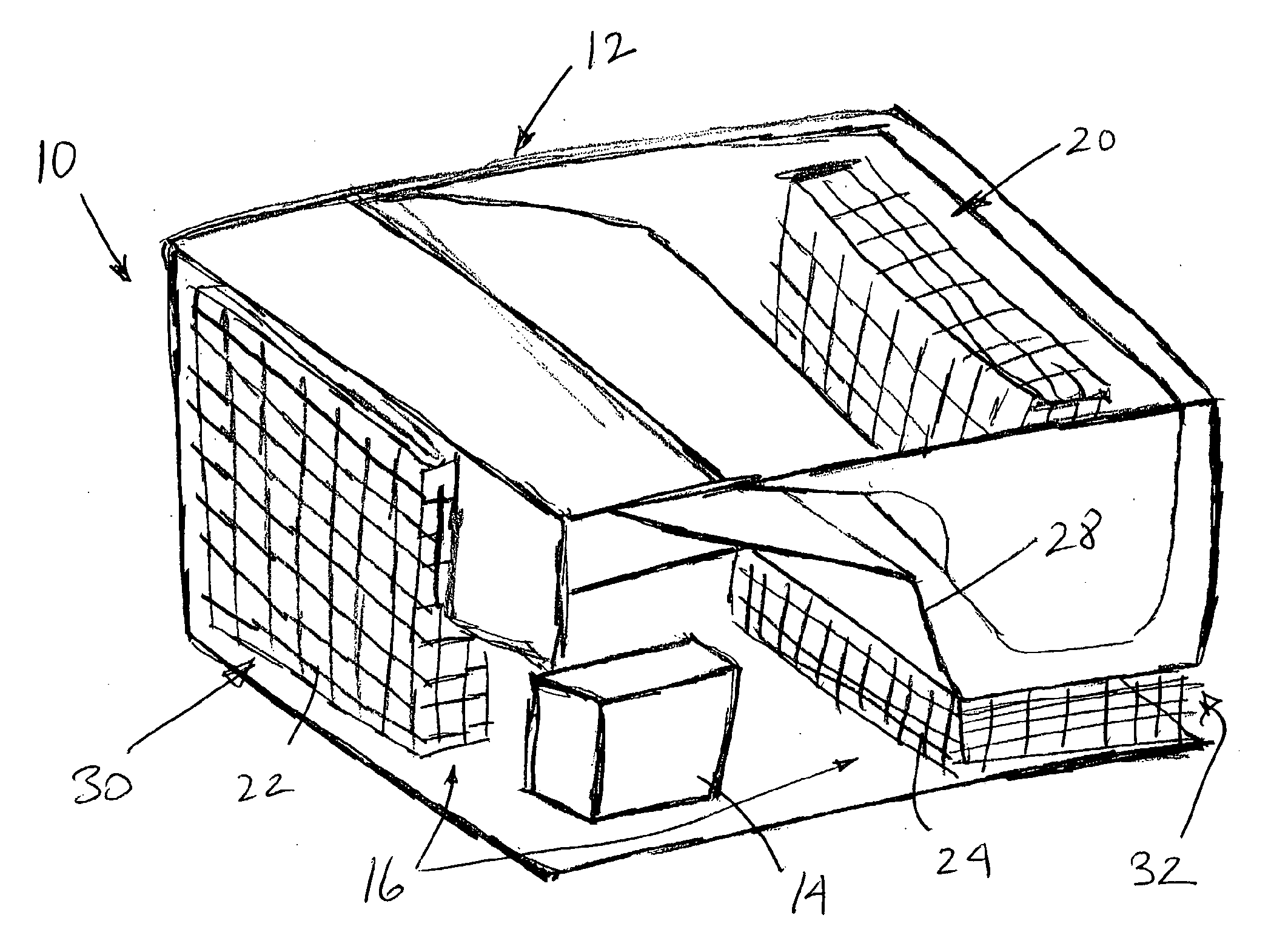
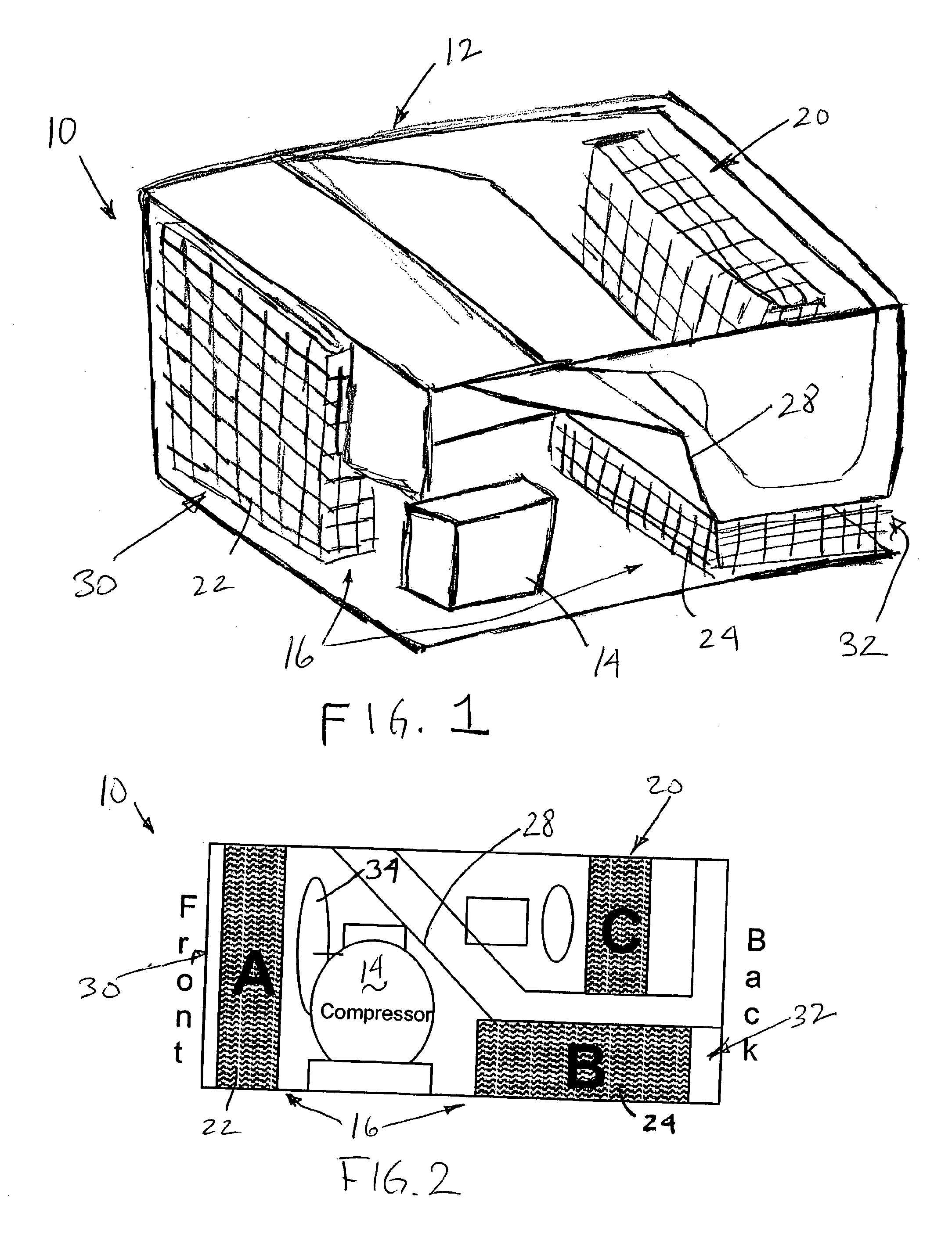
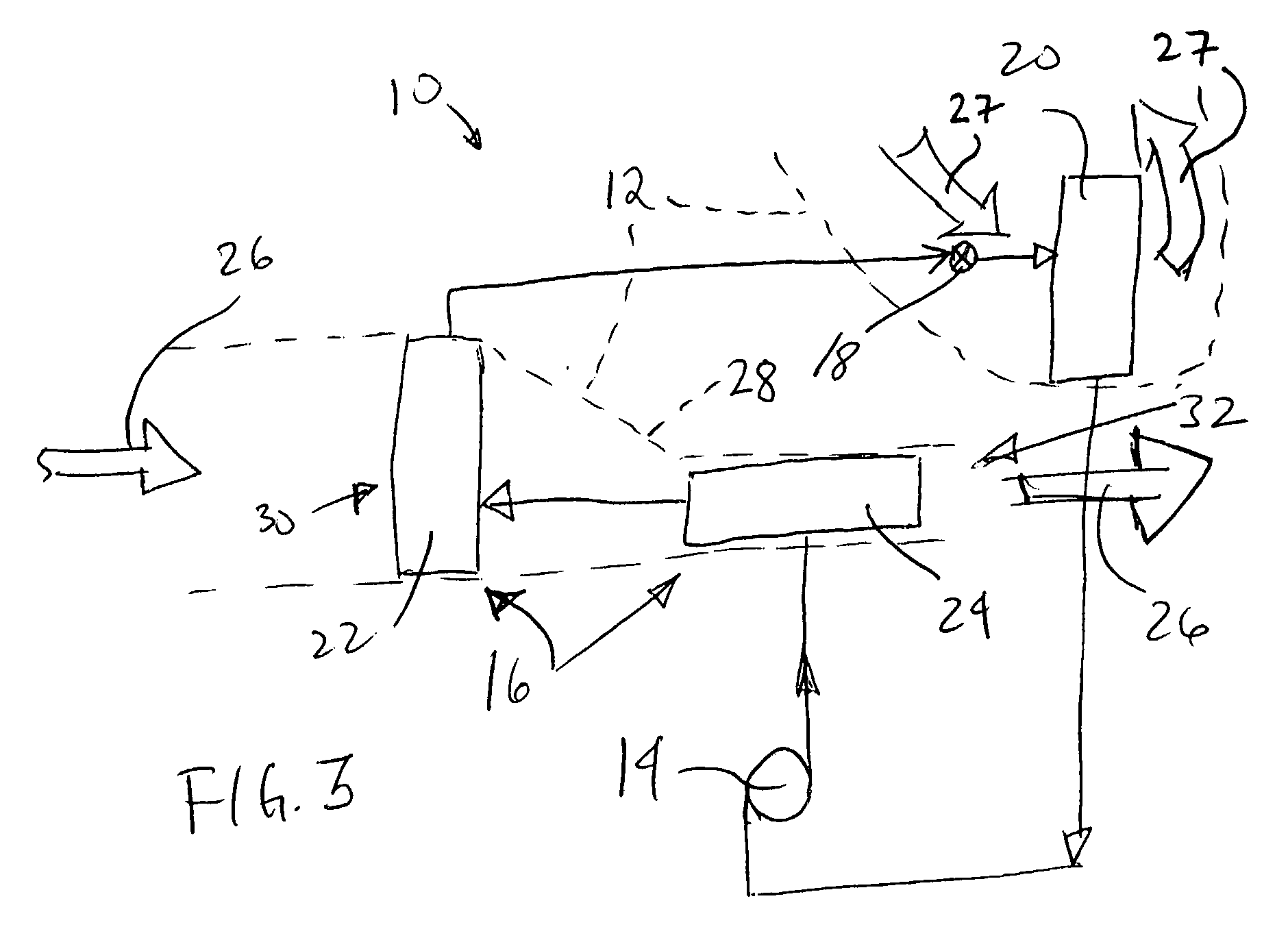
[0013]As set forth above, the greater the area of heat exchanger contact with heat exchange medium such as air, the greater the efficiency in operation of a vapor compression system. In accordance with the present invention, greater contact area between the heat exchanger and heat exchange medium is obtained by utilizing all potentially available spaces within a particular vapor compression system to house additional components of a heat exchanger, such that the heat exchanger is implemented in a series or plurality of heat exchange components. In this manner, small available spaces are nevertheless utilized to increase heat exchange efficiency and, therefore, efficiency of the overall system.

[0014]FIG. 1 shows a system in accordance with the present invent...


PUM


Abstract

A refrigeration system includes a compressor for driving a refrigerant along a flow path in at least a first mode of system operation; a first heat exchanger along the flow path downstream of the compressor in the first mode; a second heat exchanger along the flow path upstream of the compressor in the first mode; and a pressure regulator or expansion device in the flow path downstream of the first heat exchanger and upstream of the second heat exchanger in the first mode, wherein the first heat exchanger comprises a plurality of heat exchanger components arranged along a flow path of heat exchange fluid for the first heat exchanger. The heat exchanger components can be positioned in smaller available areas within the unit and thereby use space more efficiently.

Description

CROSS-REFERENCE TO RELATED APPLICATIONS[0001]This application claims the benefit of the filing date of earlier filed Provisional Application Ser. No. 60 / 663,917 filed Mar. 18, 2005. Further, copending application docket 05-258-WO, entitled HIGH SIDE PRESSURE REGULATION FOR TRANSCRITICAL VAPOR COMPRESSION SYSTEM and filed on even date herewith, and the aforesaid Provisional Application Ser. No. 60 / 663,917, disclose prior art and inventive cooler systems. The disclosure of said applications is incorporated by reference herein as if set forth at length.BACKGROUND OF THE INVENTION[0002]The invention relates to vapor compression systems and, more particularly, to a heat exchanger configuration for such a system.[0003]In many vapor compression systems, the heat exchanger placement is very much constrained by space. For these applications, the efficiency of the system is often low in comparison to a system with a properly sized heat exchanger due to the large temperature difference between...

Claims


Application Information

Patent Timeline
IPC IPC(8): F25B1/00
CPCF25B6/04F25B9/008F25B2309/061F25D19/02F25D2500/02F25D2317/0651F25D2317/0661F25D2323/00264F25D2323/00271F25D23/003
Inventor SIENEL, TOBIAS H.CHEN, YUVERMA, PARMESHHUFF, HANS-JOACHIM
Owner CARRIER COMML REFRIGERATI
Why Eureka
Try Eureka