Dual bicycle braking system

Inactive Publication Date: 2008-08-07
MOON ANDY
View PDF3 Cites 1 Cited by
  • Summary
  • Abstract
  • Description
  • Claims
  • Application Information

AI Technical Summary

Benefits of technology

[0011]Another object of the present invention is to provide a means for increasing the braking force on the front tire of a bicycle after the braking force on the rear tire has reached its maximum;
[0012]A further object of the invention is to provide a means for applying a graduated increase in the braking pressure on the front tire of a bicycle to provided for more controlled stops.
[0013]An additional object of the present invention is to provide a safer bicycle braking system that permits the bicyclist to stop in a shorter distance without the rear wheel rising from the ground.

Problems solved by technology

This sometimes causes the rear wheel to rise off the ground when the rear brake is applied abruptly in emergency situations, which can cause the inexperienced bicyclist to loose control of the vehicle.
While this approach is sound, it is limited in that it involves a relatively complex mechanical relay mechanism that adds to the difficulty of manufacture and assembly of the bicycle as well as adds a source of potential mechanical brake failure or malfunction.

Method used


Image

  • Dual bicycle braking system
  • Dual bicycle braking system
  • Dual bicycle braking system

Examples


Embodiment Construction

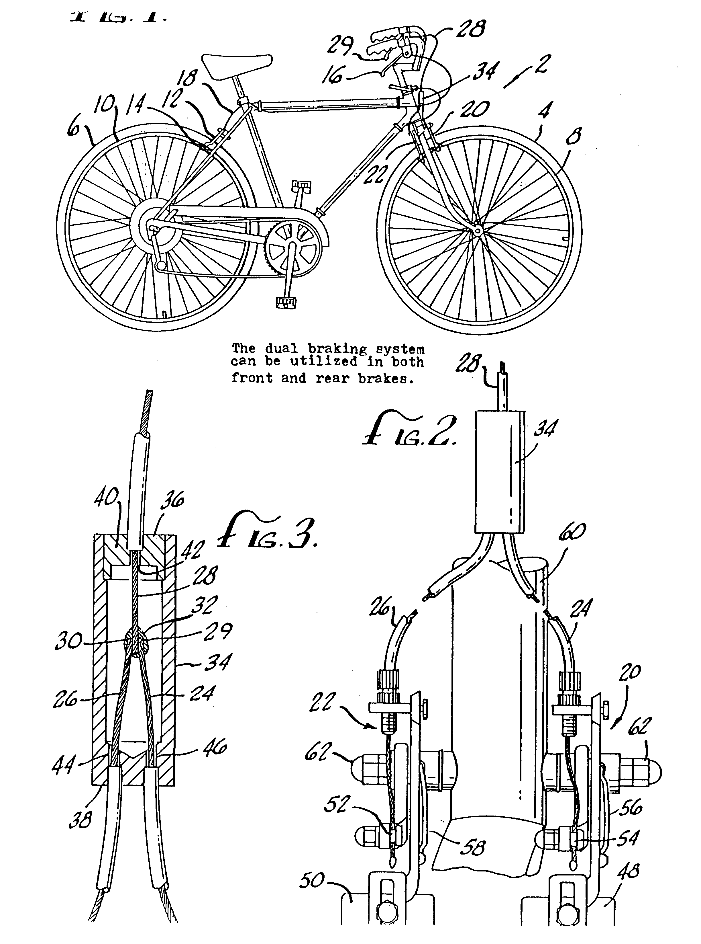
[0019]FIG. 1 illustrates a conventional bicycle 2 having a front wheel 4 and a rear wheel 6. Said front and rear wheels having front and rear rim surfaces 8 and 10, respectively. Said rear rim surface is engaged by a rear brake 12 of the conventional spring loaded caliper variety having conventional brake pads 14 (only one shown). The rear brake is controlled by a hand brake lever 16 via a rear brake cable 18. The entire rear brake system is conventional in nature.

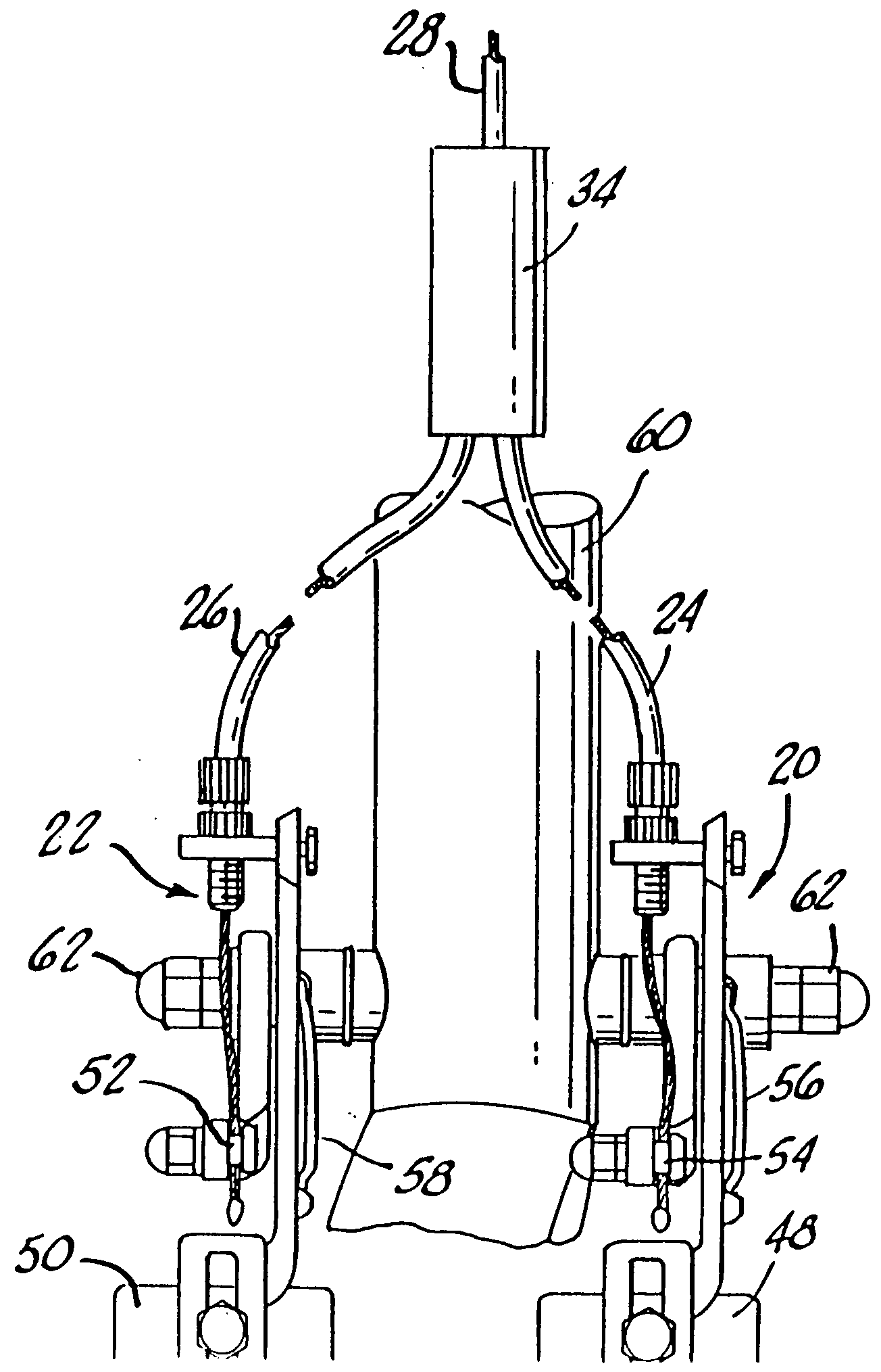
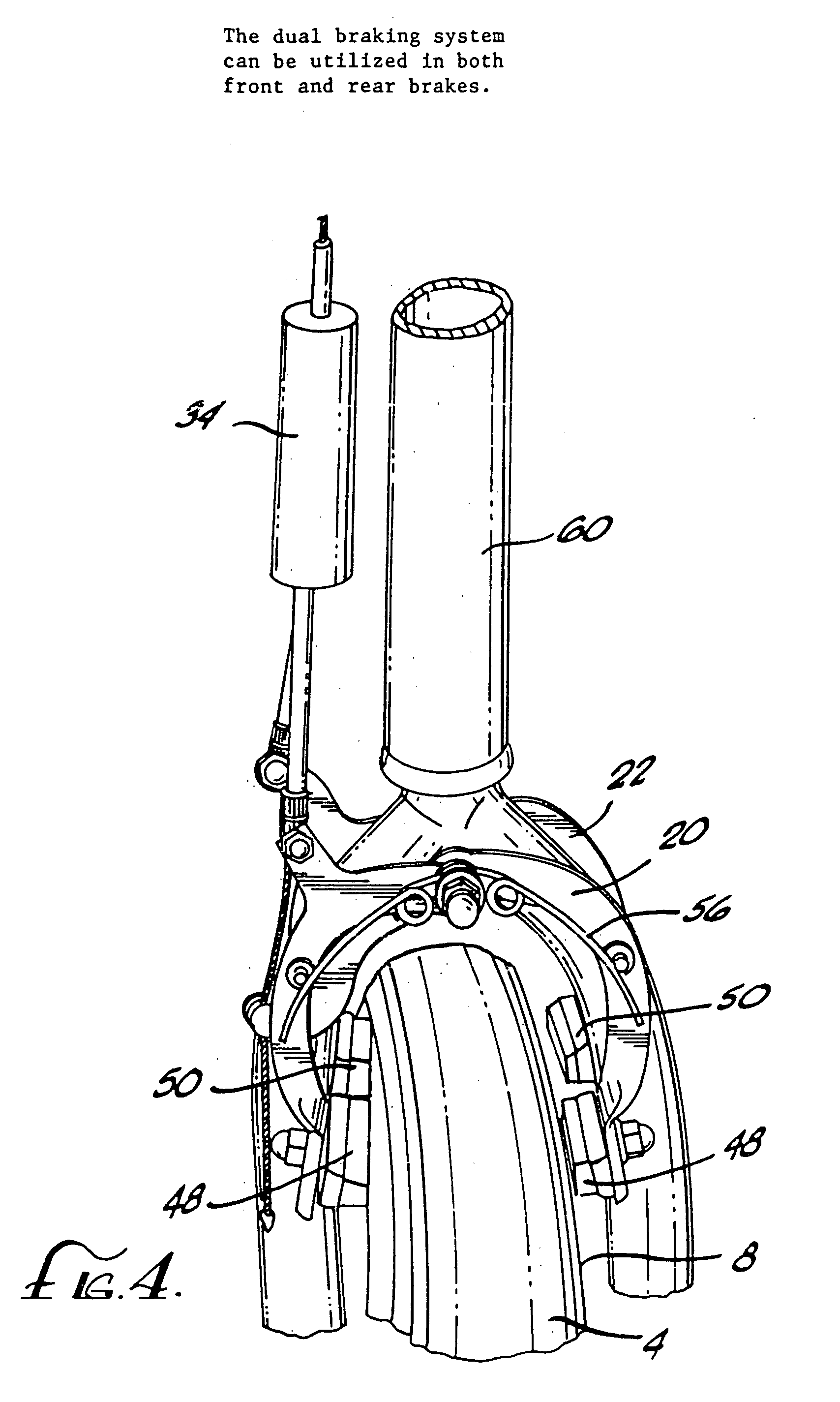
[0020]The de-acceleration of the rotation of the front wheel 4 is controlled by a dual braking system. The dual braking system is comprised of a first caliper brake 20 and a second caliper brake 22. The first caliper brake 20 is controlled by a short actuating cable 24. The second caliper brake 22 is controlled by a long actuating cable 26. The two actuating cables 24, 26 are referred to as short and long because the length of the short actuating cable 24 is less than that of the long actuating cable 26. The two actuating ...


PUM


Abstract

A dual bicycle braking system for applying greater braking force to the front wheel of a bicycle than to the back wheel, the system having front and rear brakes controlled by front and rear hand brake levers, the rear lever operationally secured to a singular rear caliper break, the front brake lever operationally secured to a primary cable, which in turn is secured to first and second actuating cables, the first actuating cable operates a first caliper brake and the second actuating cable operates a second caliper brake, both of which engage the front wheel of the bicycle to apply greater braking force to the front wheel than is applied to rear wheel by the rear caliper brake, the first actuating cable may be shorter than the second actuating cable so that the first caliper brake engages the front wheel before the second caliper brake does to provide graduated de-acceleration, or alternatively, the tension in first caliper brake may be less than in the second caliper brake to insure the same result.

Description

BACKGROUND OF THE INVENTION[0001]1. Field of the Invention[0002]This invention relates to a braking system for controlling the de-acceleration of a bicycle.[0003]2. Background of the Invention[0004]The present invention is an improvement of braking systems for bicycles. The object of most modern bicycle braking systems is to exert differential braking forces on the front and rear wheels of a bicycle. More specifically, it is generally considered preferable that the braking force on the rear tire be less than the braking force on the front tire. This rule arises out of the observation that the rear wheel has a tendency to skid when greater force is applied to the rear wheel than is applied to the front wheel. This sometimes causes the rear wheel to rise off the ground when the rear brake is applied abruptly in emergency situations, which can cause the inexperienced bicyclist to loose control of the vehicle.[0005]It has also been observed that once the rear wheel begins to skid, furth...

Claims


Application Information

Patent Timeline
IPC IPC(8): B62L3/00
CPCB60T7/102B60T1/06
Inventor MOON, ANDY
Owner MOON ANDY
Why Eureka
Try Eureka