Brake booster

Inactive Publication Date: 2011-12-08
ROBERT BOSCH GMBH
View PDF6 Cites 39 Cited by
  • Summary
  • Abstract
  • Description
  • Claims
  • Application Information

AI Technical Summary

Benefits of technology

[0021]It can furthermore be provided that the boosting ratio, that is, a ratio of actuator force to muscle power, and/or the relationship between the displacement travel and the relative deflection to be adjusted, is adjusted as a function of a speed and/or an acceleration of the booster body and/or of the input element. The terms “speed” and “acce

Problems solved by technology

For that reason, they can be used without an underpressure pump in motor vehicles with diesel engines, which for struc

Method used


Image

  • Brake booster
  • Brake booster
  • Brake booster

Examples


Example

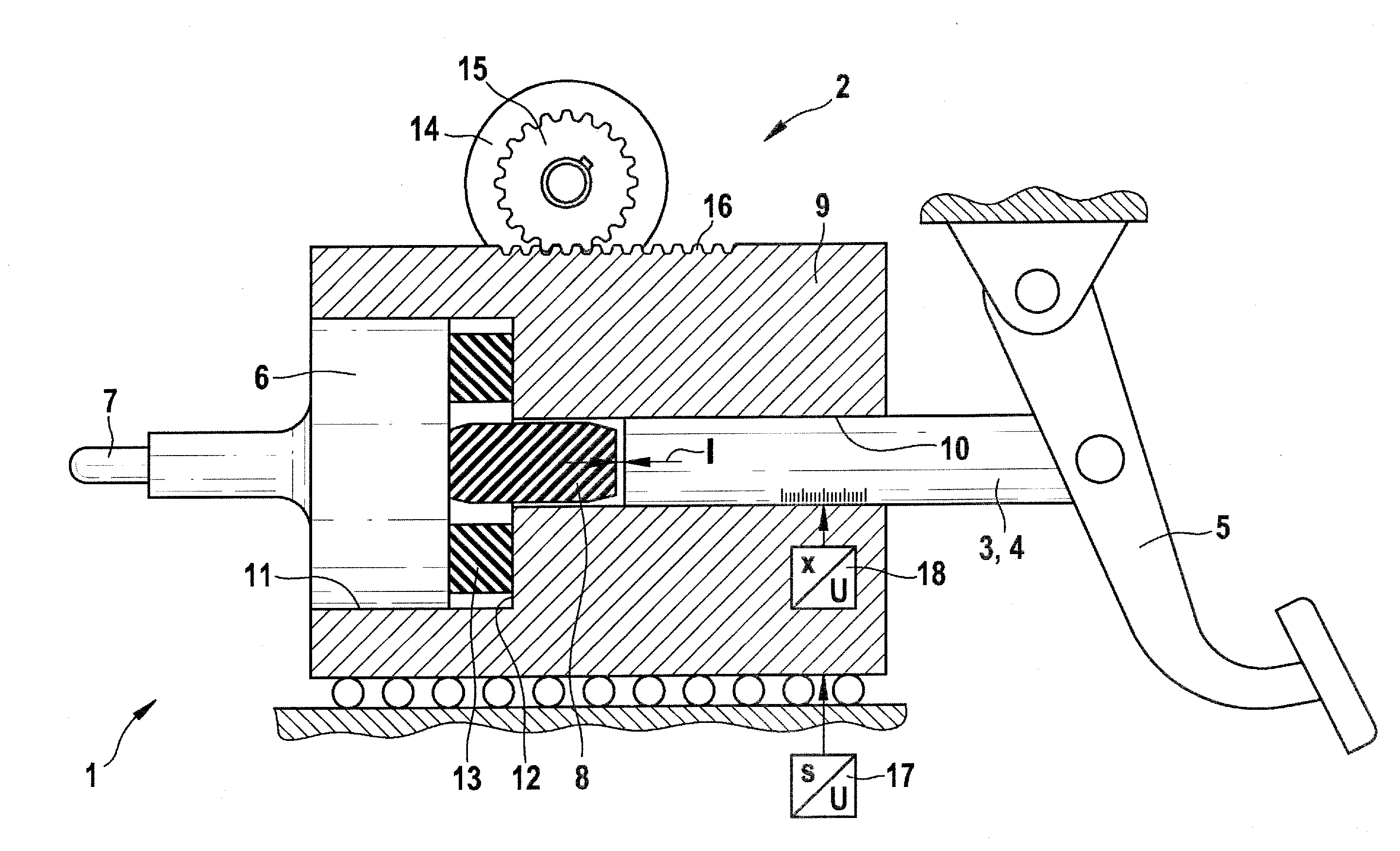
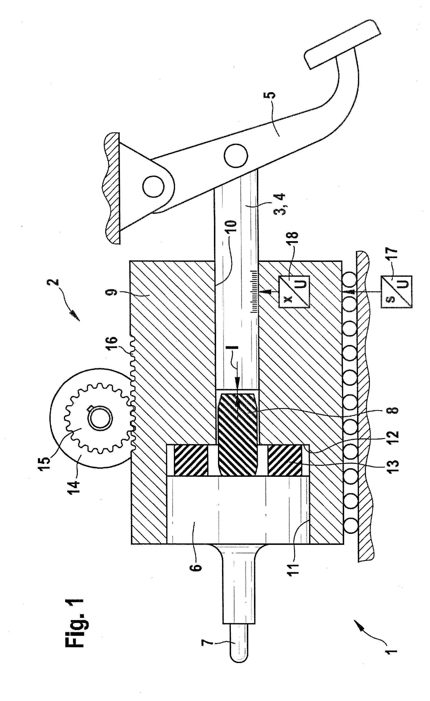
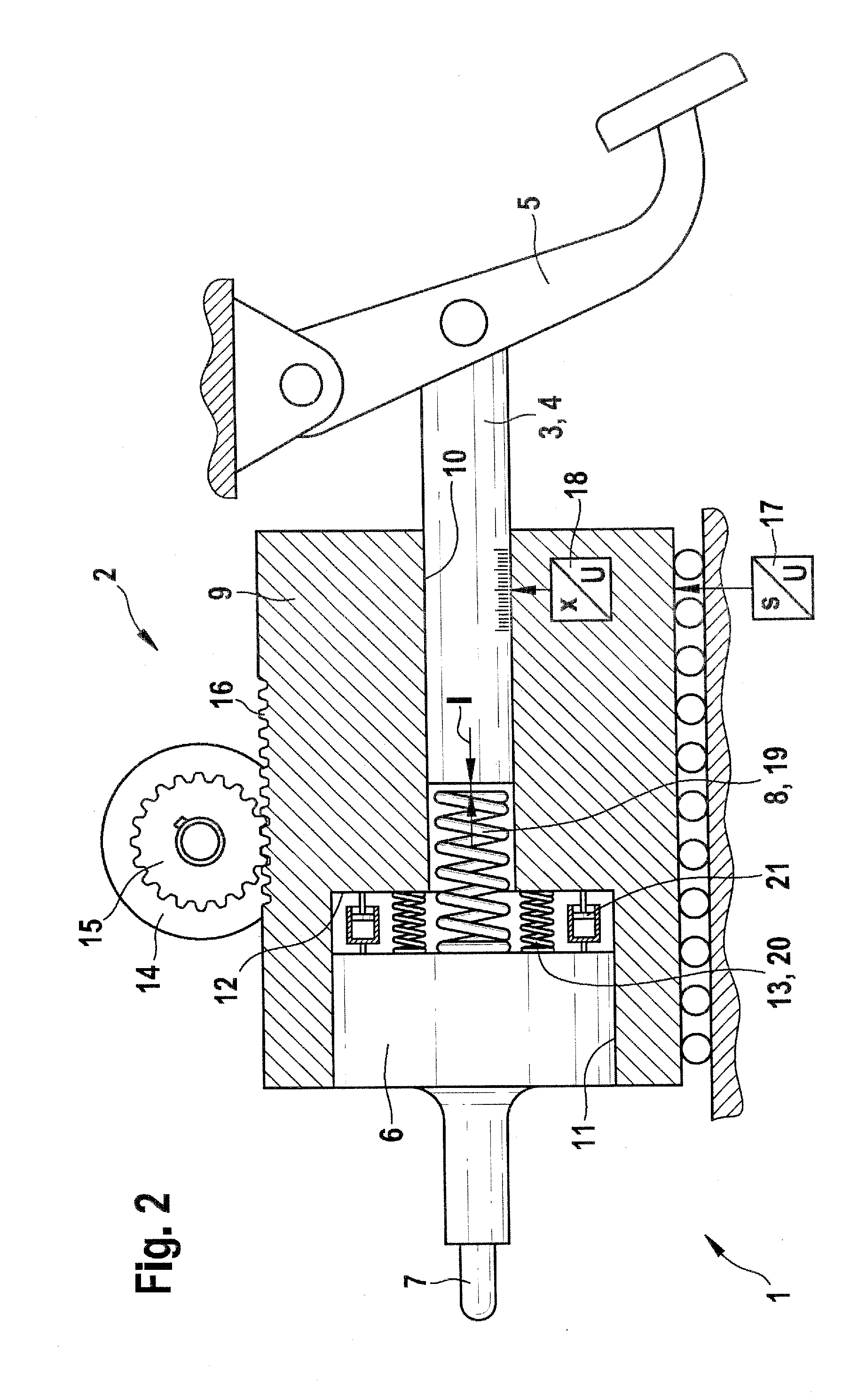
[0026]The brake booster 1 according to the invention, shown in FIG. 1, is an electromechanical brake booster 1, having an electromagnetic actuator 2, to be explained hereinafter, and a piston rod 3 that can also be conceived of in general as an input element 4 that is actuatable by muscle power. The piston rod 3 is connected in articulated fashion to a brake pedal 5. The brake booster 1 furthermore has an output element 6, with a piston-shaped base and a push rod 7, with which, in a manner known per se, a primary or rod piston, not shown, of a hydraulic master cylinder, also not shown, of a hydraulic vehicle brake system can be subjected to an actuation force.

[0027]Between the output element 6 and the piston rod 3 is a rubber-elastic boltlike transmission element 8. Via the transmission element 8, a muscle power, which is exerted on the piston rod 3 by the brake pedal 5, can be transmitted to the output element 6 of the brake booster 1. The transmission element 8, which has elastic ...


PUM


Abstract

The invention relates to an electromechanical brake booster having a piston rod to be actuated using muscular power, and an electromechanical actuator. Muscular power acting upon the pedal rod is transmitted via an elastic transmission element, for example a spring element, and the actuator power is transmitted separately thereof via its proper elastic transmission element which has for example a number of spring elements and dampers arranged in parallel thereto. The controllable brake booster is operated depending on a variable representing the relative deviation of the booster body and the input element. The brake booster according to the invention allows the adjustment of a booster characteristic which is variable in a wide range and which inter alia can depend on an actuation path, an actuation speed and/or an actuation acceleration. The switch-over to different modes, for example a sports mode, is also possible.

Description

PRIOR ART[0001]The invention relates to a brake booster, having the characteristics of the preamble to claim 1, which is intended in particular for motor vehicles. Within the scope of this invention, the term “control” also includes regulation.[0002]Underpressure brake boosters are conventional in passenger cars today; they have an underpressure chamber with a diaphragm in their interior, which divides the underpressure chamber into two compartments. In both compartments, underpressure prevails, that is, pressure that is lower than the ambient pressure. Upon brake actuation, one of the two compartments is subjected to ambient air (not necessarily at ambient pressure, but at ambient pressure only with maximum force boosting), as a result of which a force is exerted on the diaphragm that is exerted as external force in addition to muscle power on a piston of a hydraulic master cylinder. The underpressure chamber having the diaphragm can be conceived of as an actuator, namely as a pneu...

Claims


Application Information

Patent Timeline
IPC IPC(8): B60T13/66B60T13/58
CPCB60T7/042B60T13/745B60T13/575B60T8/3265
Inventor VOLLERT, HERBERTHOENLE, STEPHAN
Owner ROBERT BOSCH GMBH
Why Eureka
Try Eureka