Spindle motor having a fluid dynamic bearing system

a bearing system and spindle motor technology, applied in the direction of bearings, shafts, bearings, etc., can solve the problems of limited mechanical stability, high cost, and complex manufacturing of such motors with stationary shafts and conical bearings, and achieve the effect of improving the circulation of bearing fluid

Inactive Publication Date: 2008-08-07
MINEBEA CO LTD
View PDF7 Cites 22 Cited by
  • Summary
  • Abstract
  • Description
  • Claims
  • Application Information

AI Technical Summary

Benefits of technology

[0010]The advantages of the spindle motor according to the invention are obvious. The possibility of connecting both ends of the stationary shaft to the housing or to the base respectively considerably increases the mechanical stability and stiffness of the bearing system compared to a bearing system having a rotating shaft. The technically mature and constructionally rather simple principle of the single plate design can nevertheless be maintained, thus allowing this kind of spindle motor to be assembled at low cost, since only a few costly machined parts are required.
[0013]At least one channel extending substantially in an axial direction can further be disposed in the hub and / or the sleeve-shaped part, the channel acting as a recirculation channel and connecting the inner section of the bearing gap to the outer section of the bearing gap. This allows the bearing fluid to circulate freely within the two sections of the bearing gap. On at least one end of the bearing gap, preferably at the end at which the tapered seal is provided, an active pumping seal can further be provided, the pumping seal being defined by pumping patterns formed between the bearing bush and hub. These pumping patterns support the sealing effect of the capillary seal and the circulation of the bearing fluid in the two sections of the bearing gap.
[0014]In place of the capillary seals, active pumping seals alone may be provided as an alternative, such as are also known in the prior art and therefore not described in more detail here. A person skilled in the art would thus easily be able to determine the position and design of the pumping patterns in the bearing gap.
[0016]To improve the circulation of the bearing fluid around the thrust plate, the thrust plate may have at least one bore that connects the opposing end faces of the thrust plate to each other.

Problems solved by technology

A disadvantage is their limited mechanical stability since the bearing cannot be connected to the housing at both ends.
The manufacture of such motors having a stationary shaft and conical bearing is both complex and expensive.

Method used


Image

  • Spindle motor having a fluid dynamic bearing system
  • Spindle motor having a fluid dynamic bearing system
  • Spindle motor having a fluid dynamic bearing system

Examples


Embodiment Construction

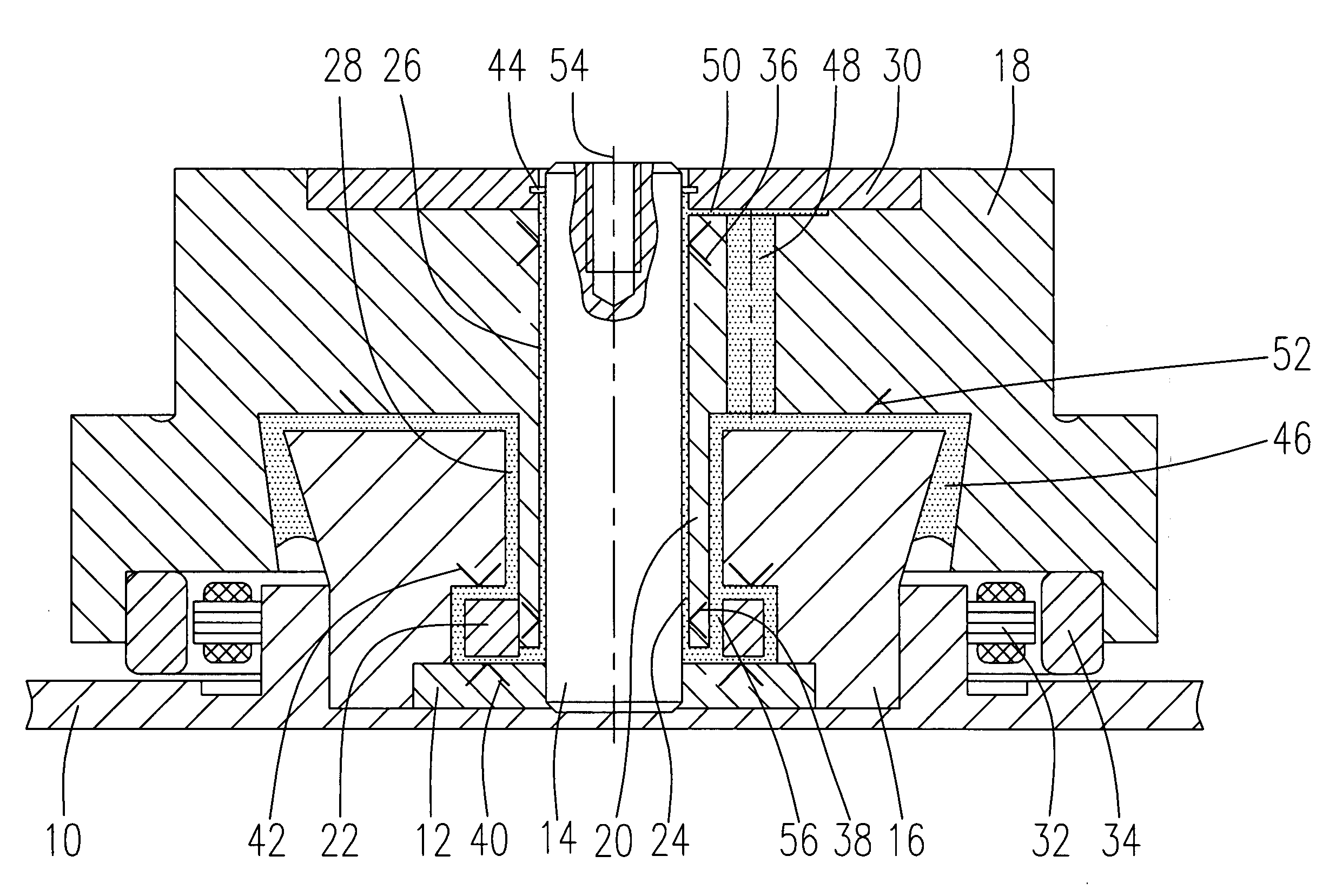
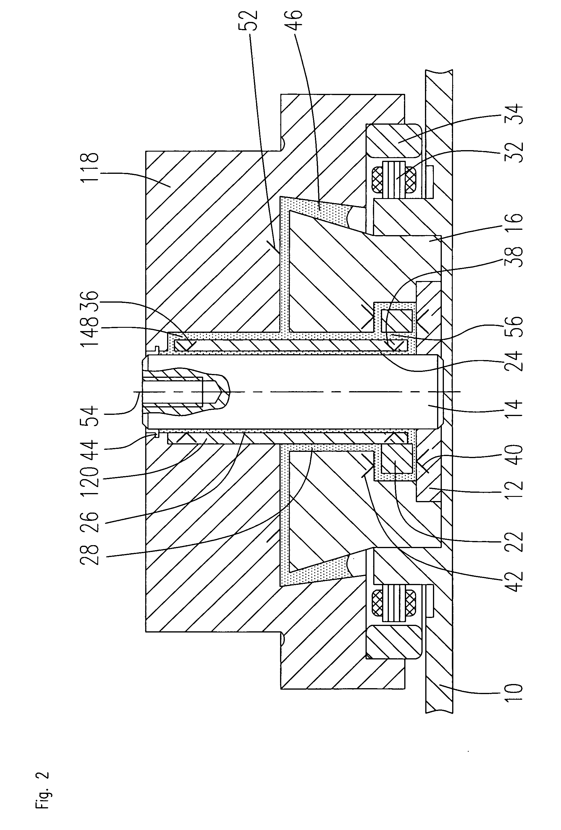
[0019]FIG. 1 shows a spindle motor according to the invention that comprises a base 10 taking the form of a baseplate or a base flange. The baseplate 10 has an annular rim into which a bearing bush 16 is pressed or bonded. The lower end of the bearing bush 16, which abuts the base 10, is sealed by a mounting plate 12. The mounting plate 12 has a central bore in which a shaft 14 is held. The hub 18 of the motor is approximately cup-shaped in cross-section and has a central bore in which the shaft 14 is accommodated. The hub 18 comprises a sleeve-shaped part 20 that is integrally formed as one piece with the hub and disposed between the outside circumference of the shaft 14 and the inside circumference of the bearing bush 16. A thrust plate 22 is attached to the free end of the sleeve-shaped part 20. The thrust plate 22 is located in a recess defined by the bearing bush 16, the mounting plate 12 and the sleeve-shaped part 20.

[0020]The hub 18 is rotatably supported about the shaft 14. ...


PUM


Abstract

The invention relates to a spindle motor having a fluid dynamic bearing system that comprises a base (10), a stationary shaft (14) that is connected to the base (10), a bearing bush (16) that is connected to the base (10) and disposed at a spacing about the shaft (14), a hub (18) having a sleeve-shaped part (20) and a cylindrical bore for receiving the shaft (14), a thrust plate (22)) that is disposed at one end of the sleeve-shaped part (20; 120), wherein the sleeve-shaped part and the thrust plate are disposed between an inside circumference of the bearing bush (16) and the outside circumference of the shaft (14). A bearing gap (24) containing bearing fluid is provided between the mutually opposing surfaces of the shaft (14), the hub (18), the thrust plate (22) and the bearing bush (16) that fully encloses the sleeve-shaped part (20) and the thrust plate (22) and has two open ends, there is at least one fluid dynamic radial bearing (36; 38) formed by the associated bearing surfaces of the shaft (14) and the hub (18) or the sleeve-shaped part (20), at least one fluid dynamic axial bearing (40; 42) formed by the associated bearing surfaces of the thrust plate (22), the base (10) and / or the bearing bush (16), and an electromagnetic drive system (32; 34).

Description

BACKGROUND OF THE INVENTION[0001]The invention relates to a spindle motor having a fluid dynamic bearing system used particularly for hard disk drives.PRIOR ART[0002]Spindle motors having fluid dynamic bearing systems can essentially be divided into two different groups: motors having a rotating shaft and a bearing system that is usually open at only one end (e.g. a so-called single plate design having an axial bearing at one end) and motors having a stationary shaft and a bearing system open at both ends.[0003]One advantage provided by the first group of motors is that they can be manufactured relatively easily and at low-cost. A disadvantage is their limited mechanical stability since the bearing cannot be connected to the housing at both ends. A bearing of this kind is revealed in DE 102 39 650 B3.[0004]An advantage afforded by the second group of motors is the possibility of connecting the stationary shaft of the spindle motor to the housing not only at one end alone, but also o...

Claims


Application Information

Patent Timeline
Patent Type & Authority Applications(United States)
IPC IPC(8): F16C32/06
CPCH02K7/088H02K7/085F16C17/107
Inventor ENGESSER, MARTINSCHWAMBERGER, STEFAN
Owner MINEBEA CO LTD
Why Eureka
Try Eureka