
Load-bearing three-dimensional structure

a three-dimensional structure and load-bearing technology, applied in the direction of mechanical machines/dredgers, paper/cardboard containers, containers, etc., can solve the problems of requiring a skilled welder and time, cumbersome solid beams, and heavy weight, etc., to achieve the effect of reducing the cost of materials, and increasing the manufacturing process

Inactive Publication Date: 2008-08-07
IND ORIGAMI INC CA US
View PDF120 Cites 34 Cited by
  • Summary
  • Abstract
  • Description
  • Claims
  • Application Information

AI Technical Summary

Benefits of technology

[0044]Yet another aspect of the present invention is directed to a method for fabricating a load-bearing three-dimensional structure, the method comprising the steps of providing a skeletal structure formed by a sheet of material having a plurality of bend lines, each bend line including a plurality of folding displacements; foldin

Problems solved by technology

Although the linkage arm may be manufactured as a solid beam, a solid beam is cumbersome, heavy, and does not make economical use of materials.
In particular, these linkage arms and support beams require significant welding along all the edges of the component parts which presents problems during the manufacturing and assembly processes.
The use of complex welding in the assembly process adds significant logistical problems and cost-concerns to the manufacturing process.
The weld lines are the key to the structural integrity of the linkage arm and thus require a skilled welder and time.
Modern robotics can limit welding errors and decrease manufacturing time; however, such robots require significant investment and add manufacturing complexity.
Welding robots are costly and cumbersome.
Given the size of the equipment needed for high-temperature welding, once the body shop is configured, it can not be easily moved.
Furthermore, every time an engineering change is made, additional time and money investment will be required to reconfigure the manufacturing process.
Having the welding done away from the assembly line also adds to manufacturing time.
In addition to manufacturing issues, welded beams present shipping, assembly, and repair concerns.
Because the arms require skilled labor and heavy machinery to manufacture, they must be manufactured near the machine assembly line or shipped as an assembled unit.
In comparison to shipping and handling of sheet stock, shipping an entire linkage arm greatly increases costs and logistical problems.
Additionally, in the field, repair of linkage arms and beams can be more inefficient than the original manufacturing process.
Shipping an entire linkage arm can be costly.
However, this requires a highly-skilled welder to be at the site.
A problem also arises from the handling and accurate positioning of the several parts in place when welding or bonding them together.
The entire process can take significant time and extends downtime when a linkage arm fails.
Since the slits can be laid out on a flat sheet of material precisely, the cumulative error from multiple bending decreases.
In addition to other limitations discussed in detail in the applications mentioned above, the slit- and groove-based bending of sheet material described by Gitlin et al. and St.
Louis have several problems under loading.
Thus, the resulting material is overstressed and failures can occur along the bending region.
Louis can not withstand significant load forces.
Louis, the resulting three-dimensional structure could not support significant loads.
These designs are limited in application for several reasons.
First, as a result of the stresses on the straps as they are twisted during bending, they are prone to failure if any significant force is applied to the structure.
Second, these configurations also lack support for the faces.
As the strap length increases, however, the force of the straps pulling the sheet against an opposing face decreases.
Thus, such conventional slit designs require a trade-off between reduction of stresses in the strap regions and maintaining edge-to-face contact to support the structure.
Nonetheless, even this design in combination with a thick sheet material does not have sufficient strength to support high loads for use as a linkage arm or load beam.
Prior art sheet material designed to be bent into a three-dimensional structure have several limitations preventing their use in such high-load applications.
First, folding displacements in general lack the rigidity of a weld.
The structure is thus prone to wobble or collapse when high forces are applied.
Folding technology also does not easily allow the formation of shapes such as an “I-beam,” which has a superior ratio of strength to material use than prior folding technology shapes.
Furthermore, prior art sheet designs can not accommodate load-bearing junctions, such as pivot mounts, for attachment to other structures.
Prior art designs do not have the strength at each end to support a shaft or fastener imposing a high lateral and torsional forces.

Method used


Image

  • Load-bearing three-dimensional structure
  • Load-bearing three-dimensional structure
  • Load-bearing three-dimensional structure

Examples


Embodiment Construction

[0058]Reference will now be made in detail to the preferred embodiments of the invention, examples of which are illustrated in the accompanying drawings. While the invention will be described in conjunction with the preferred embodiments, it will be understood that they are not intended to limit the invention to those embodiments. On the contrary, the invention is intended to cover alternatives, modifications and equivalents, which may be included within the spirit and scope of the invention as defined by the appended claims.

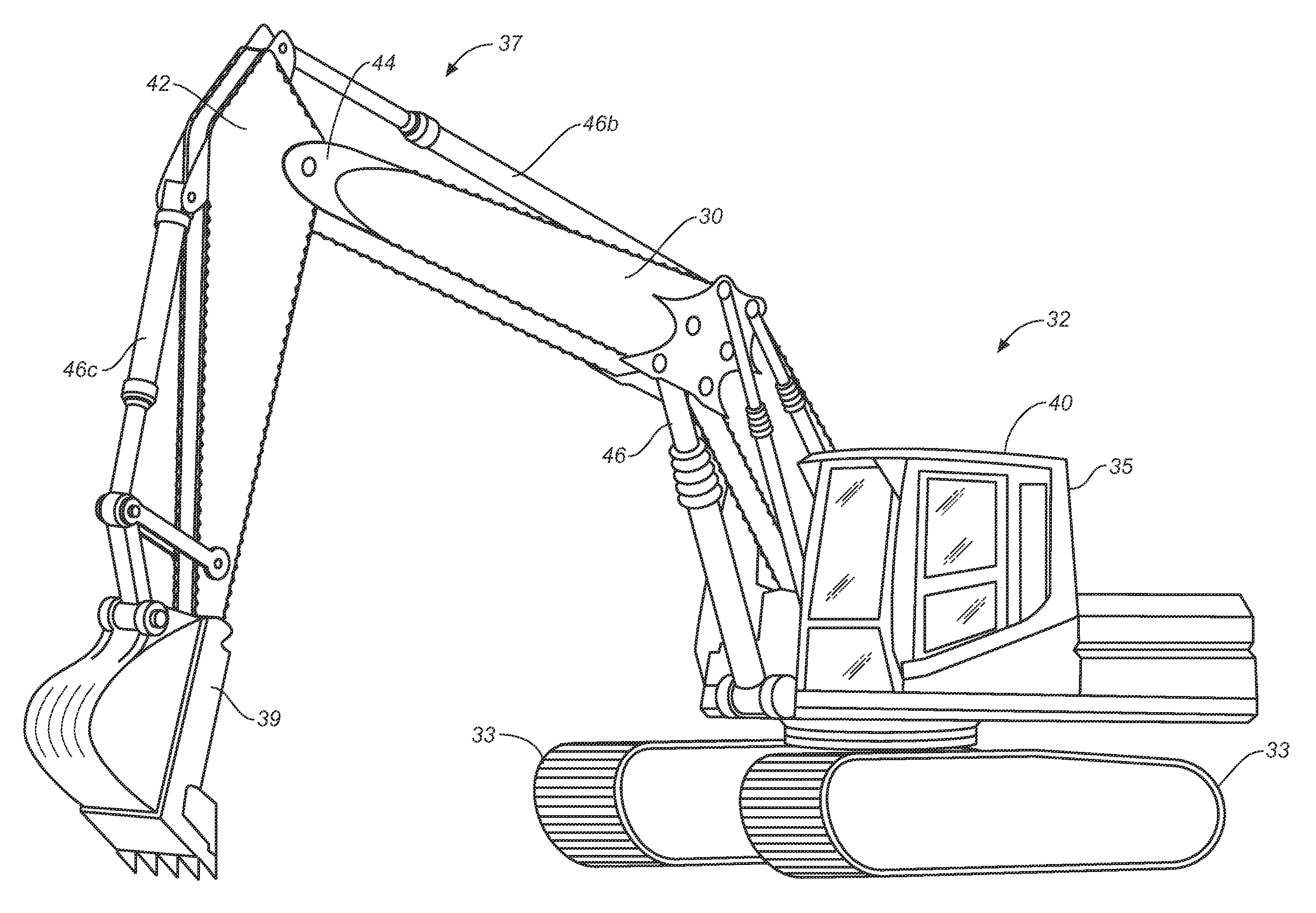
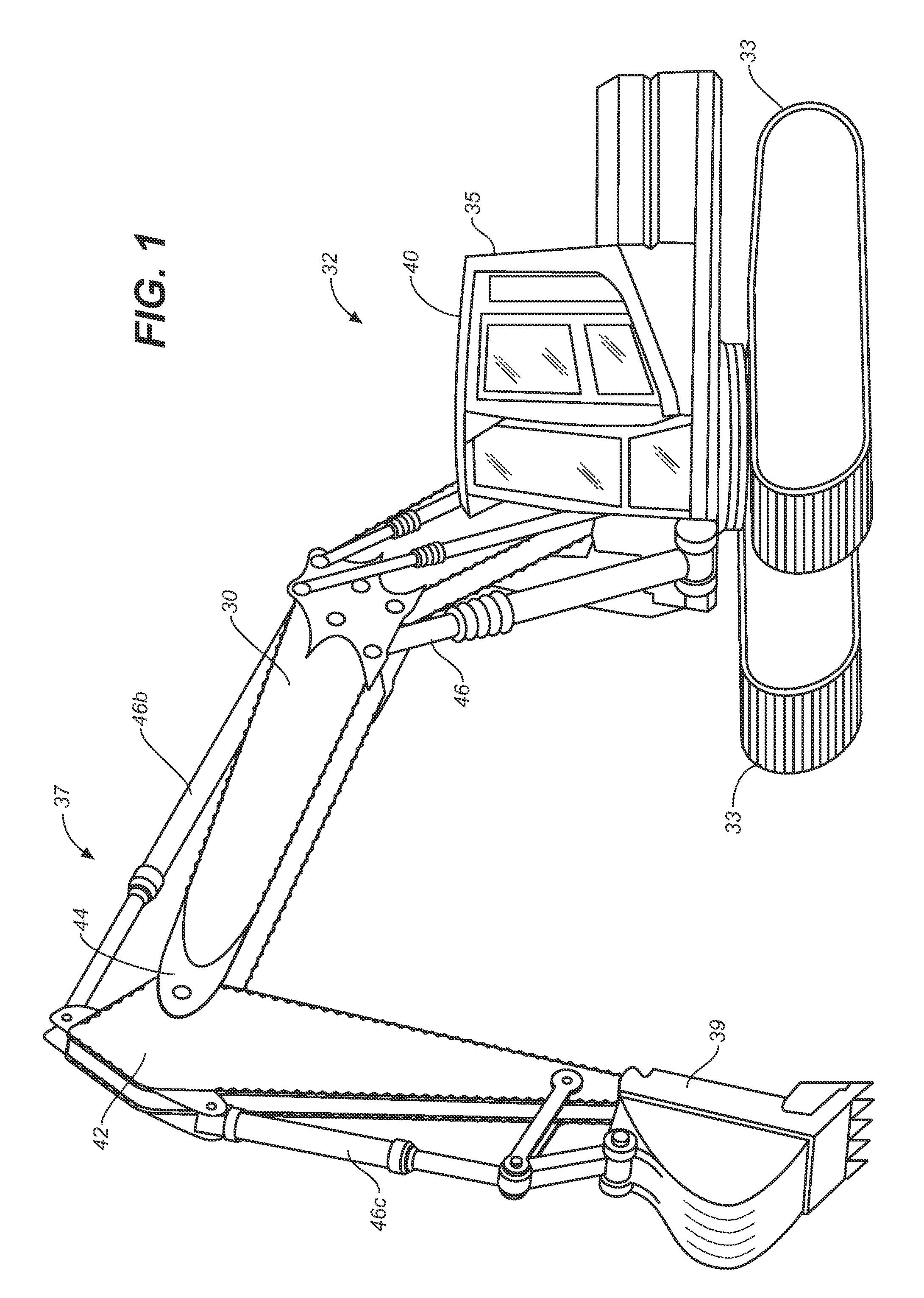
[0059]Turning now to the drawings, wherein like components are designated by like reference numerals throughout the various figures, attention is directed to FIG. 1 which illustrates a three-dimensional linkage arm formed from a substantially two-dimensional single sheet of material in accordance with the present invention, which structure is generally designated by the numeral 30. While the illustrated embodiment is a high load-bearing linkage arm for a digging...


PUM

PropertyMeasurementUnit
Forceaaaaaaaaaa
Structureaaaaaaaaaa
Shapeaaaaaaaaaa

Abstract

A load-bearing three-dimensional structure including a skeletal structure formed by a sheet of material having a plurality of bend lines, each bend line including a plurality of folding displacements, wherein the sheet of material is bent along the bend lines into a box-section; and a reinforcing member configured for substantially surrounding a portion of the skeletal structure when bent into a box-section to reinforce the structural integrity of the skeletal structure. A method of manufacturing the three-dimensional structure is also disclosed.

Description

CROSS-REFERENCES TO RELATED APPLICATIONS[0001]This application claims priority to U.S. Provisional Patent Application No. 60 / 889,262 filed Feb. 9, 2007.[0002]This application is also a Continuation-in-Part of U.S. patent application Ser. No. 11 / 411,440 filed Apr. 25, 2006, which is a Divisional of U.S. patent application Ser. No. 10 / 861,726 filed Jun. 4, 2004 (now U.S. Pat. No. 7,032,426), which is a Divisional of 10 / 672,766 filed Sep. 26, 2003 (now U.S. Pat. No. 7,152,449), which is a Continuation-in-Part of U.S. patent application Ser. No. 10 / 256,870 filed Sep. 26, 2002 (now U.S. Pat. No. 6,877,349), which is a Continuation-in-Part of U.S. patent Ser. No. 09 / 640,267 filed Aug. 17, 2000 (now U.S. Pat. No. 6,481,259).[0003]This application is also a Continuation-in-Part of U.S. patent application Ser. No. 11 / 180,398 filed Jul. 12, 2005, which claims priority to U.S. Provisional Patent Application No. 60 / 587,470 filed Jul. 12, 2004, and which is a Continuation-in-Part of the above-me...

Claims


Application Information

Patent Timeline
IPC IPC(8): B66F9/075
CPCB21D5/00B21D39/037E02F3/38B21D51/52B29C53/063B21D47/01B66F9/075
Inventor DURNEY, MAX W.
Owner IND ORIGAMI INC CA US
Learn More