Metallization process and product produced thereby

a technology of metallization process and product, which is applied in the direction of chemistry apparatus and processes, weaving, transportation and packaging, etc., can solve the problems of destroying heating process, limited applicability, and inability to use hot stamping on all substrates

Inactive Publication Date: 2008-08-07
UNIFOIL CORP
View PDF2 Cites 27 Cited by
  • Summary
  • Abstract
  • Description
  • Claims
  • Application Information

AI Technical Summary

Problems solved by technology

In conventional terms, this process is known in the art as “hot stamping.” While hot stamping is beneficial for some uses, it only enjoys limited applicability.
Hot stamping may not be used with all substrates, as the heating process may be destructive.
Also, it has been found that the hot stamped foil may separate from the substrate under aggressive conditions, if not under normal use.
Such separation is undesirable as it compromises the integrity of the finished product.
Hot stamped metallic foils are also not printable.
Techniques of this type do not disclose the use of a 100% solids-containing, electron beam (EB) curable adhesive.
In addition, this technique does not permit the selective metallization, or metallization in discontinuous regions, of the substrate.
Of note, the metal layer of structures resulting from techniques of this type is exposed to the atmosphere, and not protected by a separate coating.
This presents limitations, as the areas which are not metallized, but which are protected, may suffer from undesired effects, such as reduced sharpness or color brightness, among others.

Method used


Image

  • Metallization process and product produced thereby
  • Metallization process and product produced thereby
  • Metallization process and product produced thereby

Examples


example

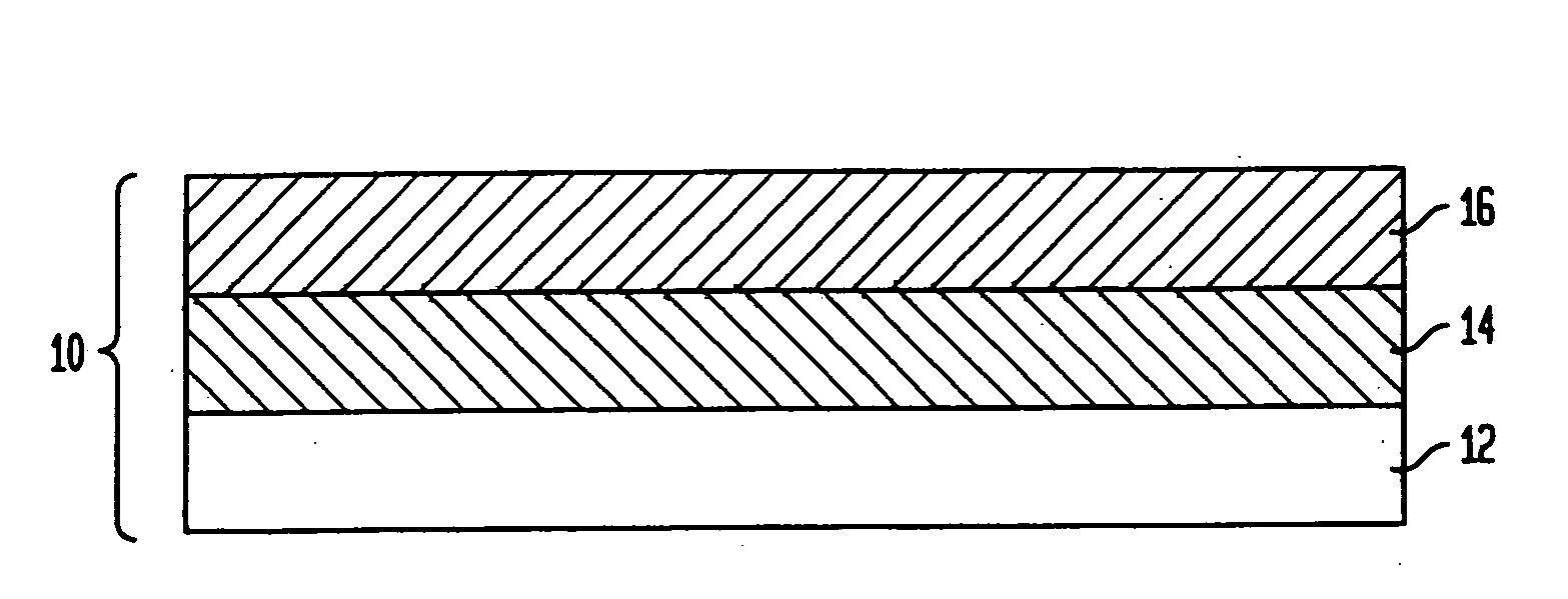
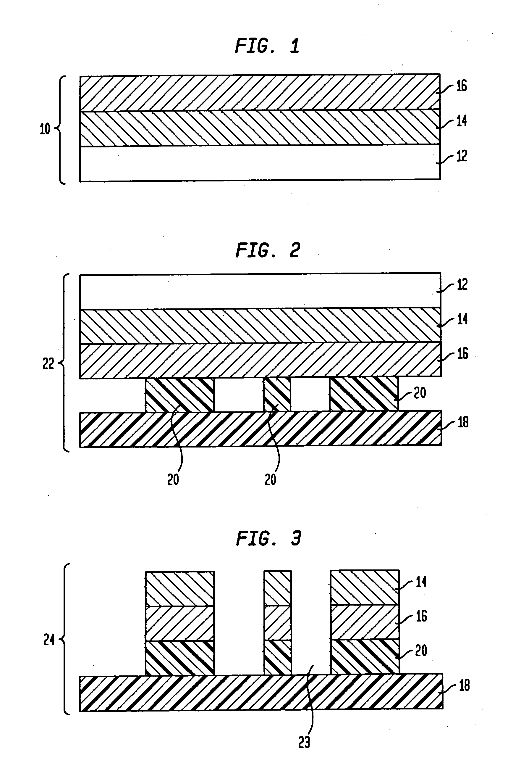
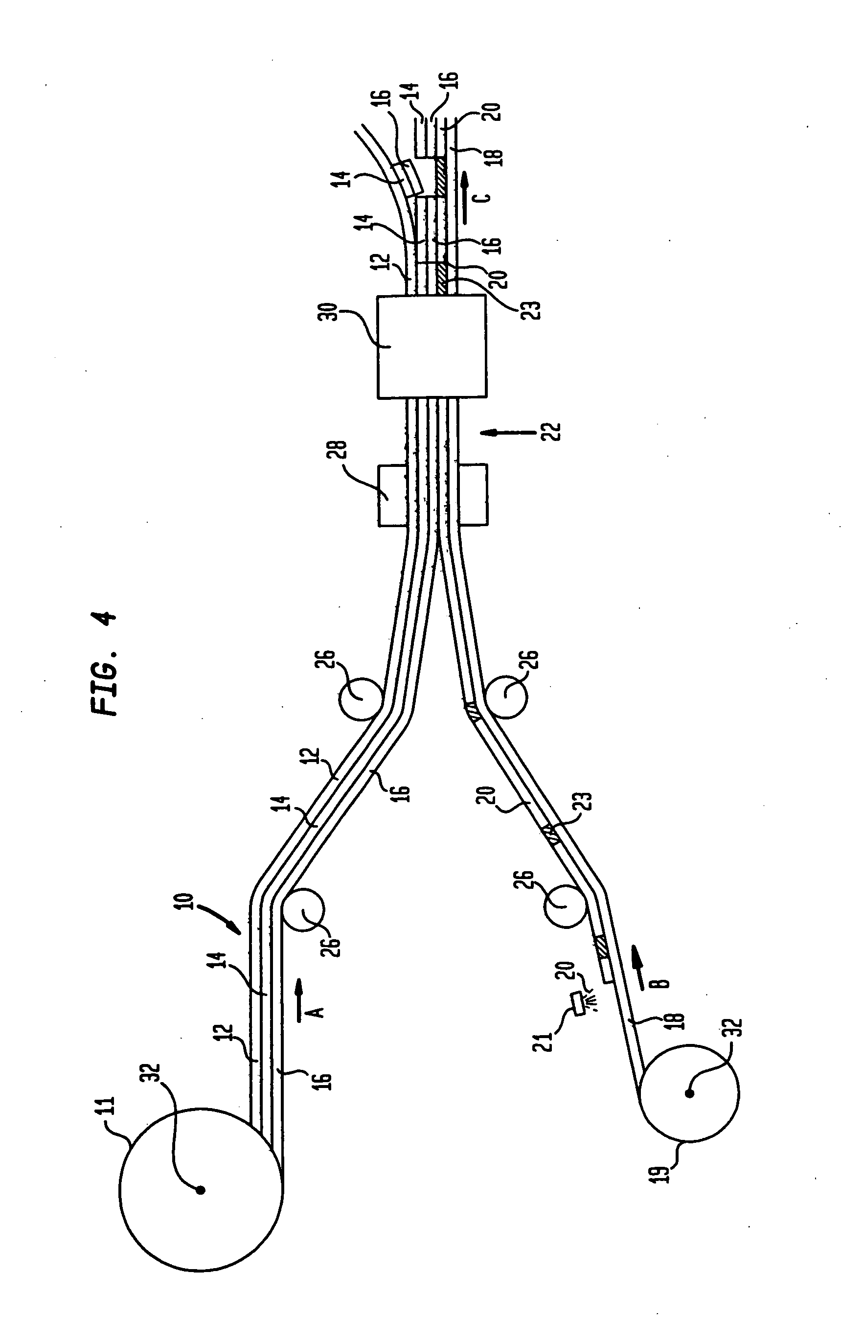
[0068]A metallized structure of the present invention, made according to a process, e.g., as illustrated in FIG. 2, is manufactured in the following manner. A 0.5 mil clear polyester transfer film is coated on one side by a gravure applicator using a 180 quad engraved cylinder, with aromatic urethane acrylate copolymer having a 70 / 30 weight ratio of urethane to acrylate components (Grancoat® 571) to a thickness of 3 microns. The breakaway coating is oven dried at 250° F. in a gas fired, hot air, low velocity oven. The dried coating layer has an elongation at break when tested in tension of 0.7%. The coated film is metallized on the coated side in a conventional vacuum metallizer to an optical density of 2.0 on the coated side of the film. The coated, metallized film is transported to an Intraroto® brand laminator equipped with an Energy Sciences Incorporated EZ Cure® brand electron beam (EB) unit. The coated film is laminated on the coated metallized side to a 6 mil white polystyren...


PUM

PropertyMeasurementUnit
distanceaaaaaaaaaa
distanceaaaaaaaaaa
elongation at breakaaaaaaaaaa

Abstract

A layered structure produced by metallizing a substrate including: (a) providing a transfer film including film layer and metal layer bonded together by a cured breakaway layer; (b) providing a substrate; (c) applying electron beam curable transfer adhesive to a portion of the substrate; (d) securing the transfer film to the substrate, where the transfer adhesive is between the metal layer and substrate, forming an intermediate product; (e) passing the intermediate product through an electron beam curing apparatus to cure the transfer adhesive; and (f) removing the transfer film. In the metallized product, the cured breakaway coating is bonded only to the metal. The cured breakaway layer preferably has a cured elongation at break, in tension, of less than about 20%. Precise metallized edges are produced, e.g., edge variation of about ±0.010 in., or better. The process can be utilized with total or selective metal transfer.

Description

CROSS-REFERENCE TO RELATED APPLICATIONS[0001]This application is a divisional of U.S. application Ser. No. 10 / 794,382, filed on Mar. 5, 2004, the disclosure of which is incorporated herein by reference.BACKGROUND OF THE INVENTION[0002]The present invention relates generally to the metallization of a substrate utilizing a transfer film, either in a selective or non-selective metallization process. More particularly, the present invention relates to such metallization processes, which include a protective coating over the metallized substrate during the metallization step, rather than as a separate procedure. Aspects of the invention also focus on an intermediate product formed from a transfer film, coating, e.g., a cured coating, and metal layer used in the transfer process. Additionally, the present invention relates to the resulting metallized substrate.[0003]Processes for the metallization of various substrates have been known for some time. These methods are typically a two-step ...

Claims


Application Information

Patent Timeline
Patent Type & Authority Applications(United States)
IPC IPC(8): B32B15/04B32B15/08B44C1/00
CPCB44C1/1737Y10T428/25Y10T428/265Y10T428/24612Y10T428/24917Y10T428/26Y10T442/654Y10T428/31692Y10T442/3382Y10T428/31507Y10T428/31681Y10T428/31678
Inventor FUNICELLI, JOSEPHGALLINO, ROBERT
Owner UNIFOIL CORP
Why Eureka
Try Eureka