Wire rope tension grid improvements

a technology of tension grid and wire rope, which is applied in the direction of scaffolding, building roofs, scaffold accessories, etc., can solve the problems of difficult, impossible, or impractical to get a ladder or man lift in an area for maintenance, and achieve the effect of reducing the stress on the cabl

Active Publication Date: 2008-08-14
INTERAMERICA STAGE
View PDF60 Cites 5 Cited by
  • Summary
  • Abstract
  • Description
  • Claims
  • Application Information

AI Technical Summary

Benefits of technology

[0004]Modularity: A wire rope tension grid is installed as a modular item, able to be removed for service and transported easily for erection. The connections to the modular attachments have been improved. Through bolts connect hanger points to the grid. This provides a hard connection as opposed to a floating clamped connection. This is a further improvement over the pieces in the past that are non-modular, being welded to their respective support hangers.
[0005]Reducing the lateral stress on the wire rope within the wire rope tension grid was a major priority. Rolled edges and chamfered through holes have aided in this regard. Even the position of the hole itself has been reconsidered, and positioned accordingly. The cable is supported over the frame support tube increasing the area of impact and lessening the stress at any particular point in the cable. This allows for a horizontal load to be applied to the wire rope.
[0006]Structural strength of the frame has likewise been improved by adding support tabs that do not interfere with the location of the wire rope. These help distribute the vertical and torsion loads that are exerted on the frame while it is in use.
[0007]The bottom portion of the hanger connections were further improved, providing streamlined outer perimeter and corner connections for safe handling and aesthetics.
[0011]Through bolts within the frame allow for a rigid connection to adjacent wire tension grid panels. This helps to prevent the frame from bowing under stresses applied by taught wire rope.
[0012]In an instance where a wire rope tension grid system is required to have the wire rope non-perpendicular and non-parallel to the frame a new way of distributing the wires had to be realized. A wire rope turn pin was added to the frame so that the wire rope can be weaved in the same way that the regular rectangular tension grids. The wire rope turn pin decreases the stress on the cable. Elliptical slots on frame for the cables further lessen pinch points.

Problems solved by technology

It is usually installed in performing art centers, black box theaters, and in locations were it is difficult, impossible, or impractical to get a ladder or man lift in an area for maintenance.

Method used


Image

  • Wire rope tension grid improvements
  • Wire rope tension grid improvements
  • Wire rope tension grid improvements

Examples


Embodiment Construction

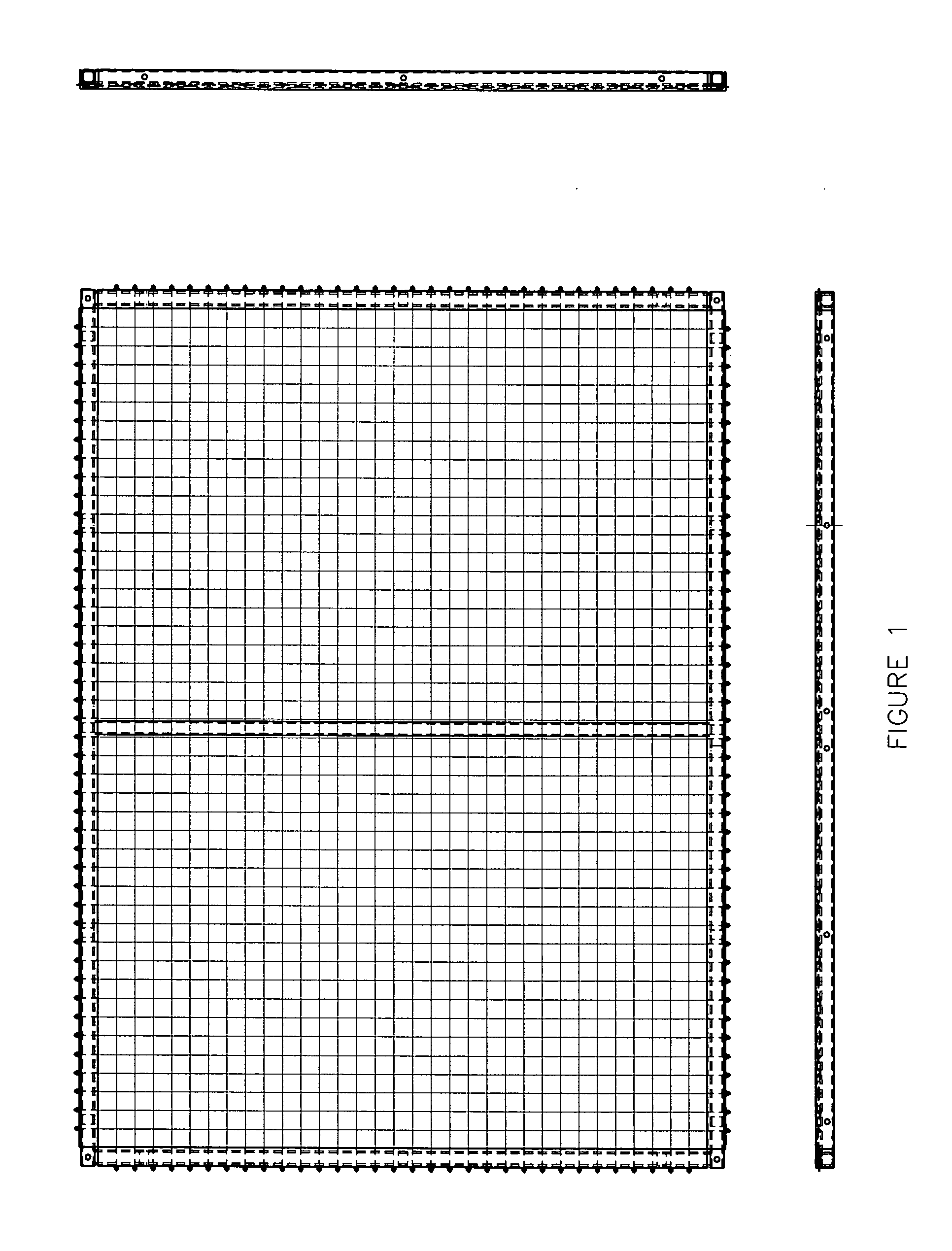
[0020]FIG. 1 displays a complete wire rope tension grid panel. These panels are constructed of mild steel tubing and mile steel angel. The dimensions of the said steel vary per application, but are most often constructed of 3 / 16″ thick 1.5″×1.5″ steel tubing with a piece of angle measuring 1.5″×1.75.″

[0021]Holes are predrilled into the angle at increments of 2″ center. These holes are 5 / 32″ in diameter. Holes are also predrilled into specific points on the tubing for modular through holes and for hanger plate bolts.

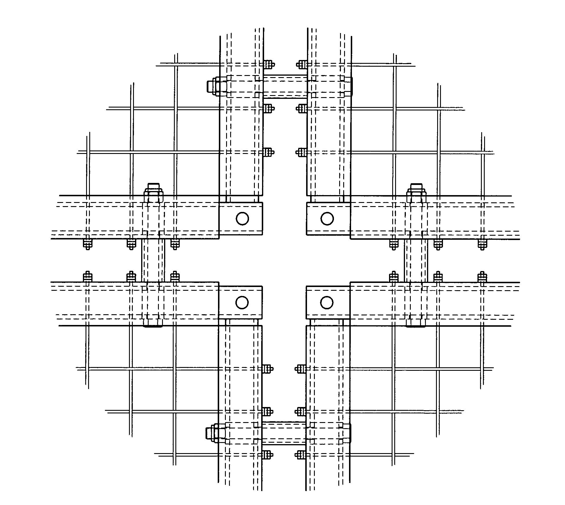
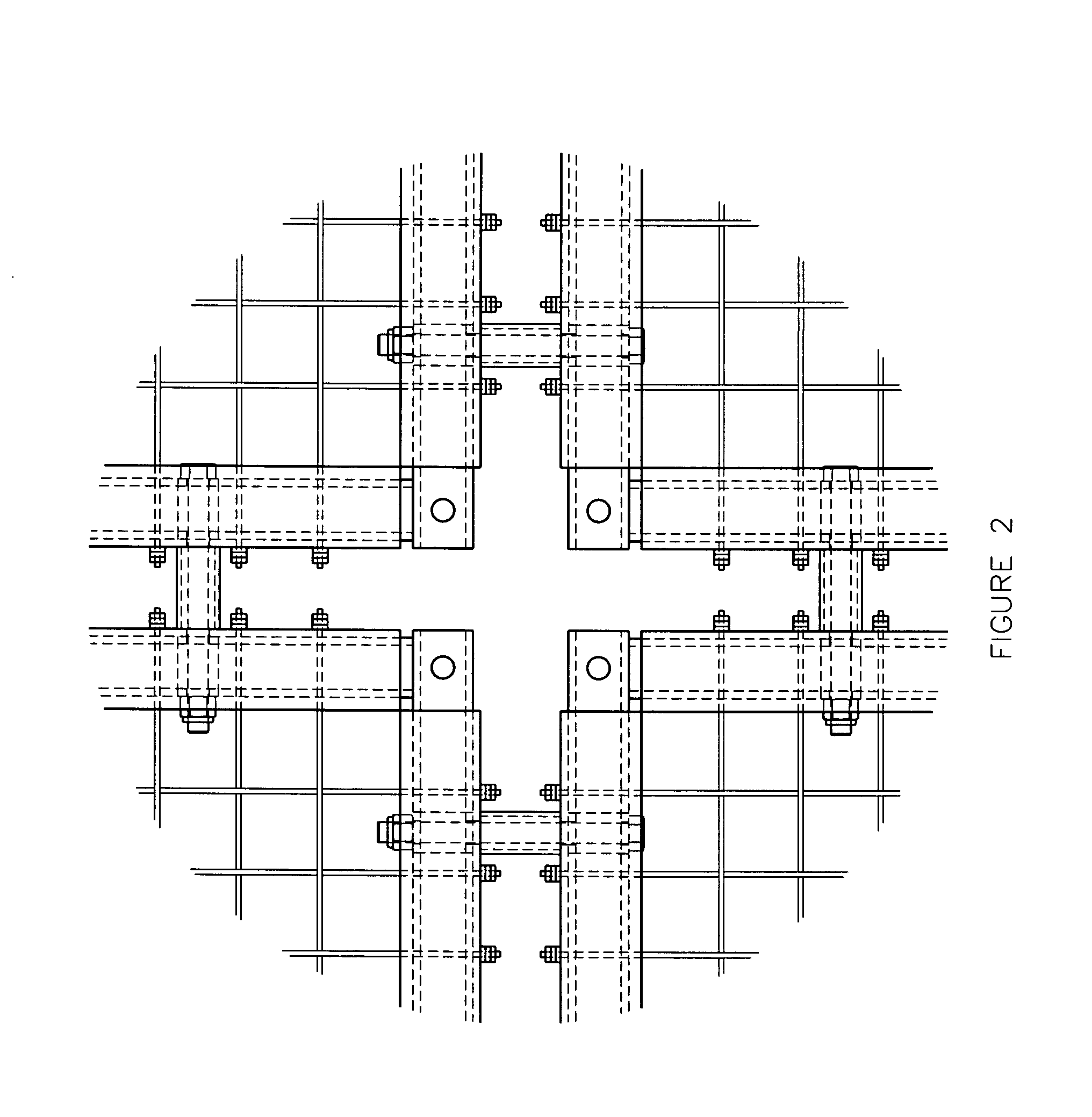
[0022]The angle is welded onto the tubing making the basic frame structure. This basic frame is reinforced by supports welded above the locations of the through holes used for modular attachments. FIGS. 2 and 3 display these supports as hidden lines.

[0023]FIGS. 4 and 4A display the use of the wire rope turn pin. If the design calls for the use of this device then a hole will be drilled into the angle and tubing. The wire rope turn pin will then be inserted into the frame ...


PUM


Abstract

A wire rope tension grid is a walking surface comprised of interwoven wire rope. The wire rope is supported by a framework of steel angle and tubing. The framework is supported by mounts that are hung from the support beams in the ceiling of a structure, often a performing art center, a television studio, a black box theater, museum dioramas, theme park scenes, live animal pens, or other entertainment venues. These grids are not intended for public usage, but rather are intended for operation staff. New improvements to these grids are listed in this document.

Description

BACKGROUND OF THE INVENTION[0001]These inventions improve the design of the current grid structure. The use, safety, and assembly of safe aerial platforms is likewise improved. The present invention is used to allow personnel safe access to high reach areas for mechanical tasks and maintenance operations, such as changing the position of theatrical lights, servicing air conditioning ducts, etc.[0002]The wire rope tension grid has been in use for decades. It is usually installed in performing art centers, black box theaters, and in locations were it is difficult, impossible, or impractical to get a ladder or man lift in an area for maintenance. Through both the use and construction of many wire rope tension grid systems, InterAmerica Stage, Inc. has made various improvements to the structures. Currently we will be releasing a new line of improved wire rope tension grids. These grids will feature both the improvements that have been made over time by our firm and new improvements that...

Claims


Application Information

Patent Timeline
Patent Type & Authority Applications(United States)
IPC IPC(8): E04B1/34
CPCA63J3/00E04G5/00A63J7/00
Inventor BLACK, MARK THOMAS
Owner INTERAMERICA STAGE
Why Eureka
Try Eureka