Stand with at least three legs

Inactive Publication Date: 2008-08-14
LEICA GEOSYSTEMS AG
View PDF9 Cites 16 Cited by
  • Summary
  • Abstract
  • Description
  • Claims
  • Application Information

AI Technical Summary

Benefits of technology

[0010]Due to this possibility to swivel the stand legs it is achieved that a stand can practically be collapsed to the size of three legs formed from flat parts and that the stand can be erected ready for use by a simple pivotal motion into positions offset in reference to each other by approx. 120° each. This is an optimal embodiment particularly for a universally used small stand. Therefore, such a stand could be easily produced form plastic injection-molded parts. The stand can then also be erected securely on rough and uneven surfaces.
[0011]In order to improve the stability of the stand on the floor it is suggested for the stand legs to be provided with lateral limits, which at least converge towards each other in the proximity of the freely projecting supporting ends of the stand legs. Therefore, these ends are formed as a tip or at least as a rounded tip.
[0013]Further, it is suggested that the stand legs are arranged at a slight distance from each other, at least in the area of the common axis. This way it is possible to produce the stand legs from a flat profile, because this allows in a simple manner a mutual pivoting around a common axis due to this distance.
[0016]Here, an advantageous design comprises that the two sections formed by the bend of the uppermost stand leg are embodied the longest and that these sections of the lowermost stand leg are embodied the shortest. This way, the legs do not disturb each other during any swiveling process and additionally an exactly aligned positioning on the ground is possible at all times.
[0019]In order to allow the stand to be advantageously used at a wall or with another support, it is provided that at least one of the stand legs, preferably the uppermost stand leg, is provided with recesses, slots, bores, or the like in the freely projecting section. This way, in a simple manner, a hooking in or fastening by another fastening means can occur.
[0021]Particularly for a wall fastening using screws with a head, it is advantageous when at least one of the stand legs, preferably the uppermost stand leg, is provided with keyhole-type recesses at the freely projecting section. The stand and / or the respective stand leg can be hooked to a wall after a screw was mounted.

Problems solved by technology

However, in all embodiments some preliminary assembly processes are necessary and the structural parts are large and expensive.

Method used


Image

  • Stand with at least three legs
  • Stand with at least three legs
  • Stand with at least three legs

Examples


Embodiment Construction

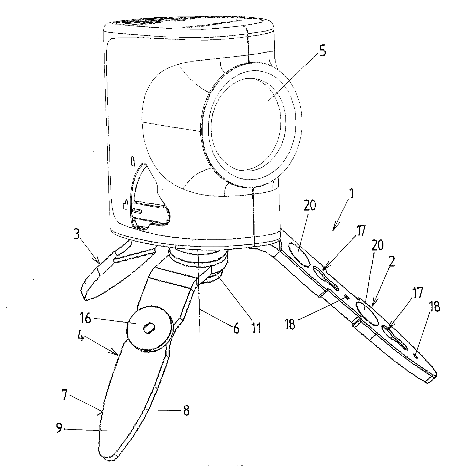
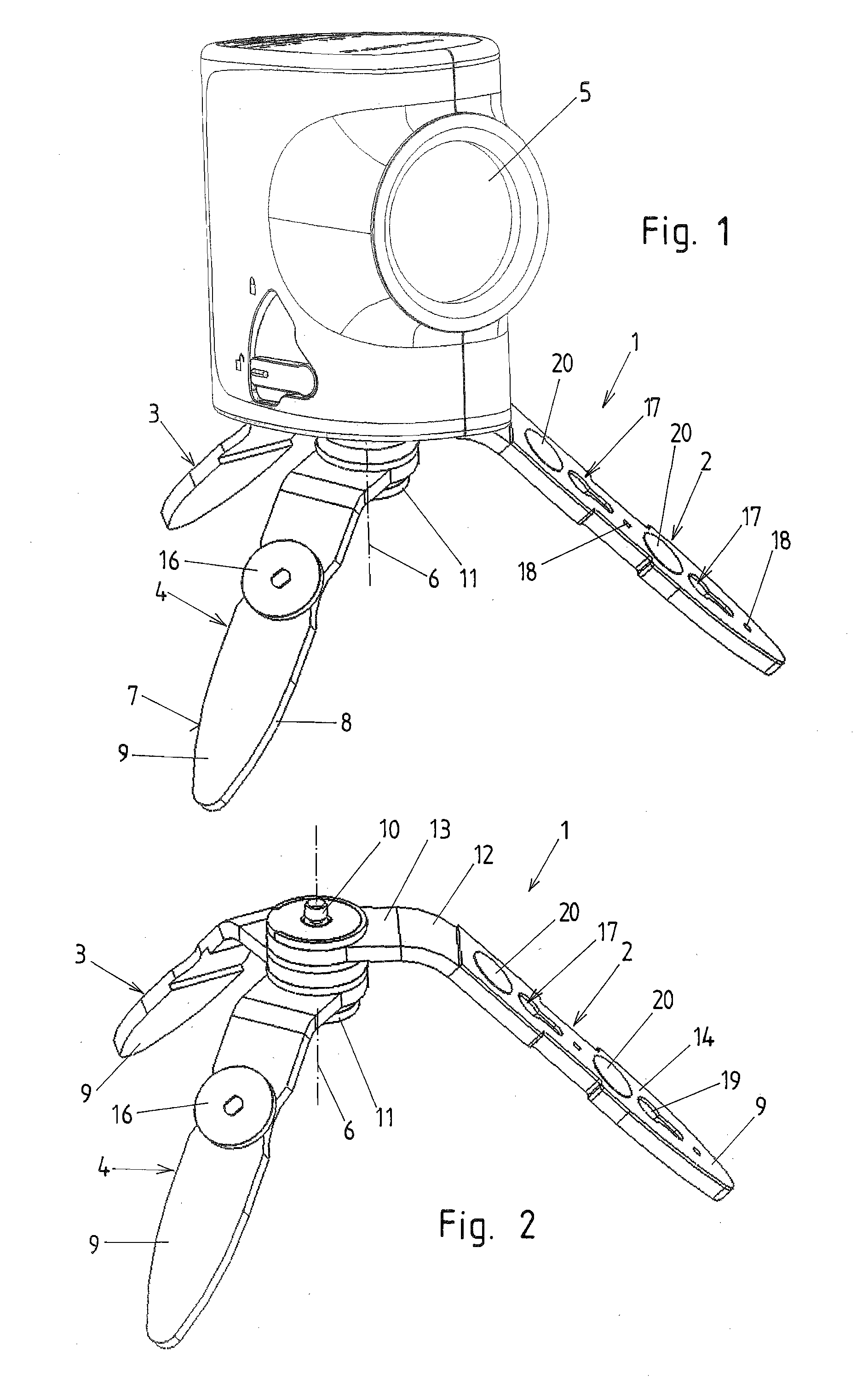
[0036]The stand 1 according to the invention includes at least three stand legs 2, 3, and 4. The stand 1 is intended to fasten a leveling, plumbing, and angular calibration instrument 5, e.g., a linear laser, point laser, or small rotary laser device. Of course, within the scope of the invention this stand can be used for other purposes as well, e.g., for fastening photo equipment, when a small stand is sufficient.

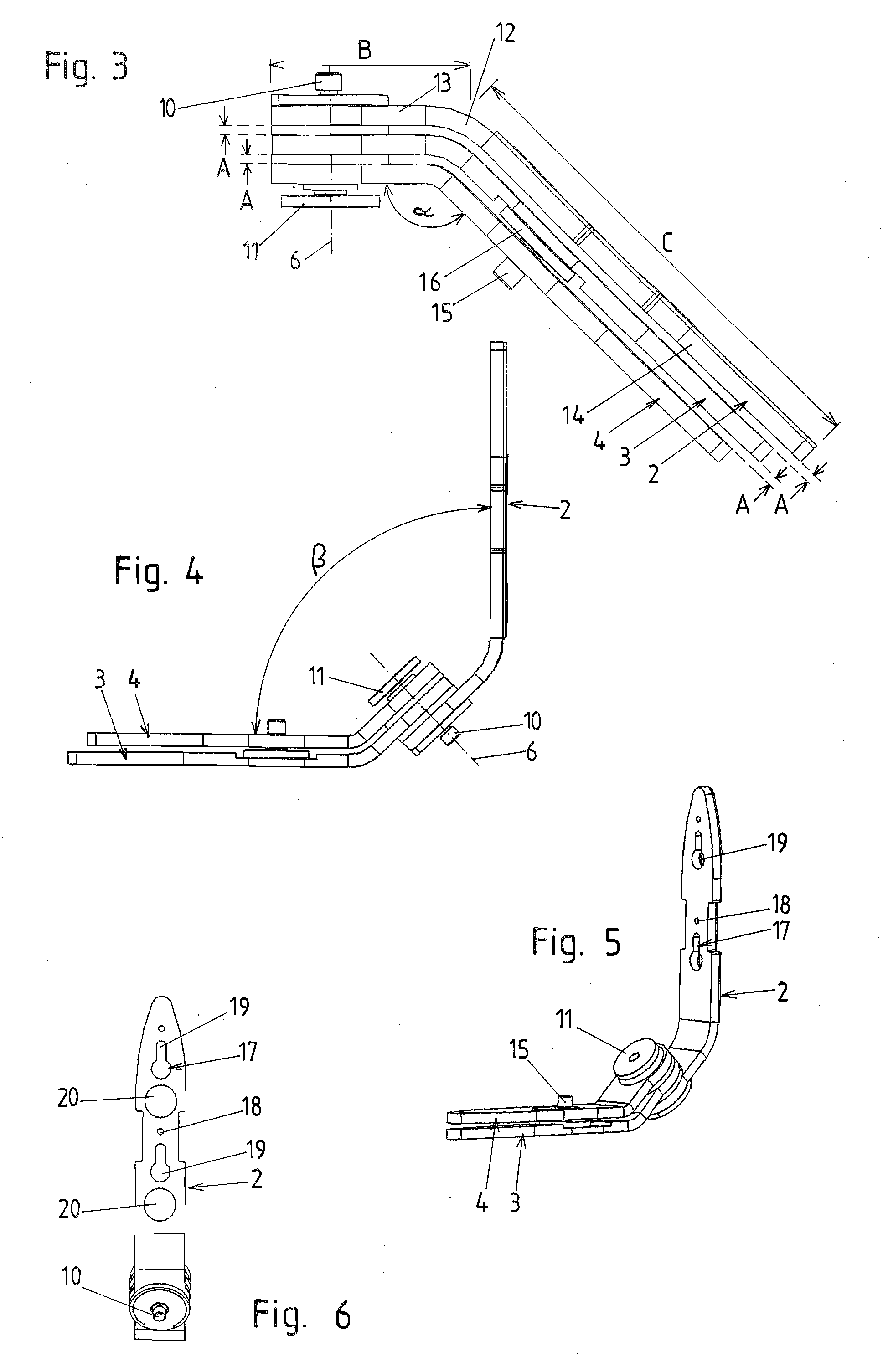
[0037]The invention provides that the stand legs with their ends facing each other are rotational around a common axis 6. Further, all stand legs 2, 3, 4 are bent by the same angle α at a distance from the axis 6.

[0038]The stand legs 2, 3, 4 have side edges 7, 8, which, at least in the proximity of the freely projecting support ends 9 of the legs 2, 3, 4, converge towards each other. Therefore, sufficient stability is given particularly when erecting it on the ground. When the stand legs 2, 3, 4 are pivoted out, as shown in FIG. 1 and FIG. 2, the instrument has a non-wobbl...


PUM


Abstract

A stand with at least three stand legs (2, 3, 4), which is embodied to fasten a leveling, plumbing, or angular calibration device (5), is provided, with the stand legs (2, 3, 4) being embodied rotational around a common axis (6) at their ends facing each other. Each stand leg (2, 3, 4) is bent by the same angle (α) at a distance from the axis (6), with a freely projecting section (14) of one leg being provided with a threaded bolt (15) freely protruding transversely thereto.

Description

CROSS-REFERENCE TO RELATED APPLICATIONS[0001]This application claims the benefit of DE 10 2007 007 041.3, filed Feb. 13, 2007, which is incorporated herein as if fully set forth.BACKGROUND OF THE INVENTION[0002]The invention relates to a stand with at least three stand legs, which is embodied for holding a leveling, plumbing, or angular calibration instrument, e.g., a linear laser, point laser, or small rotary laser device, with the stand legs at their ends facing each other being rotational around a common axis, and each of the stand legs being bent by the same angle at a distance from the axis.[0003]A number of accessories are offered for linear lasers. They are always designed to support the linear laser in reference to a desired operational position. Linear lasers are provided with a photo thread, for example. This way, the user can insert very small or normally sized photo tripods, which usually are provided with a central column, which is adjustable via a crank (vertical fine-...

Claims


Application Information

Patent Timeline
IPC IPC(8): F16M11/38
CPCF16M11/16F16M2200/08F16M11/242F16M11/22
Inventor BOGEL, GERHARD
Owner LEICA GEOSYSTEMS AG
Why Eureka
Try Eureka