
Optimal node placement for multi-dimensional profile luts for arbitrary media and halftones using parameterized minimization

Inactive Publication Date: 2010-01-26
XEROX CORP
View PDF6 Cites 9 Cited by
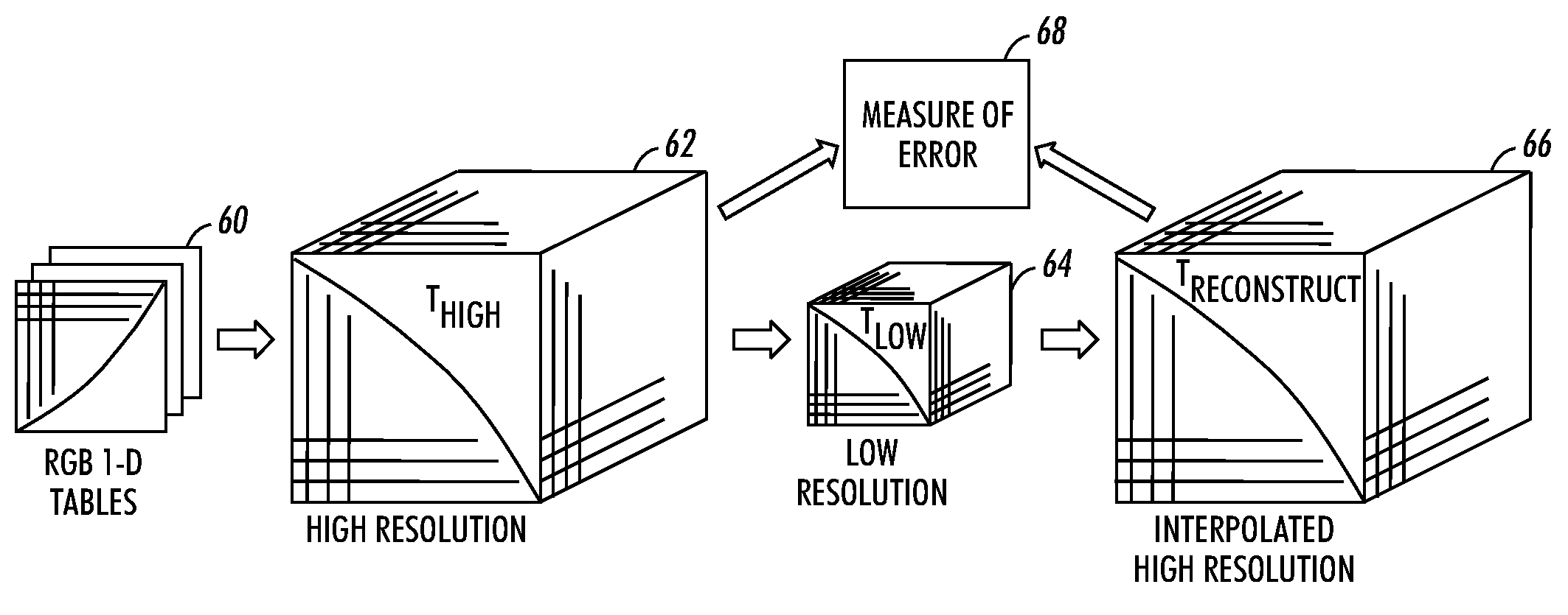
  • Summary
  • Abstract
  • Description
  • Claims
  • Application Information

AI Technical Summary

Benefits of technology

[0005]A method for optimal node placement of a color correction table is provided. A first color correction table is generated having a first number of nodes at a first set of node locations. Each of the first number of nodes has a corresponding color correction value. A second color correction table is generated having a second number of nodes at a second set of node locations corresponding to the second number of nodes. The second number of nodes is less than the first number of nodes, and each of the second number of nodes has a corresponding color correction value based on the first color correction table. A third color correction table is generated having a third number of nodes at a third set of node locations. The third number of nodes is greater than the second number of nodes, and each of the third number of nodes has a corresponding color correction value based on the second color correction table. Differences between the color correction values of the third color correction table and the color correction values of the first color correction table are determined. The differences are quantified into a measure of error, and node locations of the second set of node locations are adjusted. The procedure of generating a second color correction table, generating a third color correction table, determining differences, and quantifying the differences is repeated at least one time.
[0006]An alternate method for optimal node placement of a color correction table is also provided. A high resolution color correction table is generated. The high resolution color correction table has a number of nodes greater than the number of nodes of an output device color correction table, and each node of the high resolution color correction table ha

Problems solved by technology

However, because printers inherently have a complex, nonlinear behavior and therefore have a complex nonlinear colorimetric response, even after a printer is calibrated, the full spectrum of CMYK values and printed colors is not a completely accurate representation of the original RGB spectrum.
A discrepancy arises because the relationship between digital values that drive the printer and the resulting calorimetric response is a complex nonlinear function.
However, a table comprising such a large number of locations places a strain on computational resources.
However, due to the above-described nonlinear response of the printer, there are areas of the color correction with high curvature that are under-sampled in the table and other smooth areas of the correction that are over sampled unnecessarily.
Currently, small color correction tables result in loss of detail and higher delta E (ΔE) accuracy in the darker areas.
Heretofore, if the image quality loss was too large, higher density correction tables, i.e., larger tables, were employed to reduce the image quality loss, however, with the above-described associated drawbacks.

Method used


Image

  • Optimal node placement for multi-dimensional profile luts for arbitrary media and halftones using parameterized minimization
  • Optimal node placement for multi-dimensional profile luts for arbitrary media and halftones using parameterized minimization
  • Optimal node placement for multi-dimensional profile luts for arbitrary media and halftones using parameterized minimization

Examples


Embodiment Construction

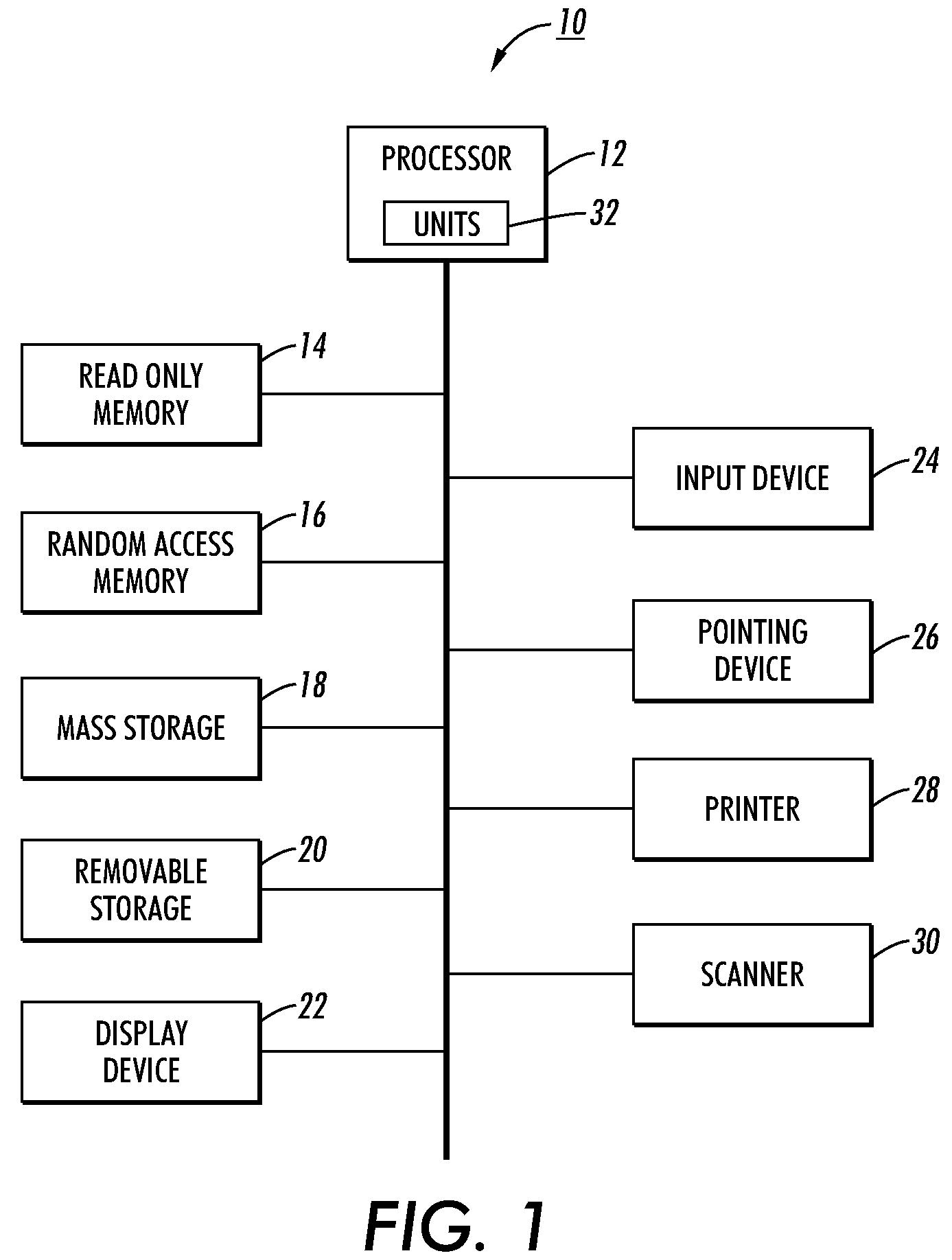
[0013]With reference to FIG. 1, a schematic block diagram is shown with an embodiment of a computer system 10 in which the herein-described method of optimal node placement can be utilized. The computer system 10 includes a processor 12, a read-only memory 14, random access memory 16, a data storage device 18 such as, e.g., a disk drive, and a removable data storage device 20 such as, e.g., a CD drive or a DVD drive. The computer system preferably includes a display device 22 such as a color monitor, an input device 24 for a user to enter commands to the computer system, a pointing device 26 such as, e.g., a mouse or trackball for manipulating a graphical user interface or other objects displayed on the display device 22. The computer system 10 may also be connected to a printer 28 and / or a scanner 30. Each of the printer 28 and the scanner 30 may be connected to the computer 10 either locally or by means of a network connection to e.g., a local area network. Processing units 32 acc...


PUM


Abstract

A method and system for optimal node placement of a color correction table first generate a high resolution color correction table. A low resolution color correction table is generated. Each node of the low resolution color correction table has a corresponding color correction value generated by interpolating the color correction values of the high resolution color correction table. A reconstructed color correction table is generated, and each of the nodes of the reconstructed color correction table has a corresponding color correction value generated by interpolating the color correction values of the low resolution color correction table using an interpolation method identical to an output device interpolation method. Differences between the color correction values of the reconstructed and the high resolution color correction table are quantified into a measure of error, and the node locations of the low resolution color correction table are adjusted, and the procedure is repeated.

Description

BACKGROUND[0001]The present application relates to the color imaging arts. It finds particular application to color correction tables as used in, e.g., printers, and will be described with particular reference thereto.[0002]Heretofore, computers and other electronic equipment such as digital cameras have typically generated three-dimensional RGB (red, green, blue) color signals. Many printers, however, are configured to receive four-dimensional CMYK (cyan, magenta, yellow, and black) signals as input and, therefore, print CMYK colors which are determined from corresponding RGB values. A lookup table is commonly provided to convert each digital RGB color signal value to a corresponding digital CMYK value before being received by the printer. However, because printers inherently have a complex, nonlinear behavior and therefore have a complex nonlinear colorimetric response, even after a printer is calibrated, the full spectrum of CMYK values and printed colors is not a completely accu...

Claims


Application Information

Patent Timeline
IPC IPC(8): G03F3/08
CPCG06T11/001H04N1/6019
Inventor SCHWEID, STUART ALANMESTHA, LALIT KESHAVFAN, ZHIGANGGIL, ALVARO ENRIQUE
Owner XEROX CORP
Learn More