Scroll Compressor

Inactive Publication Date: 2008-08-14
MITSUBISHI ELECTRIC CORP
View PDF7 Cites 4 Cited by
  • Summary
  • Abstract
  • Description
  • Claims
  • Application Information

AI Technical Summary

Benefits of technology

[0010]According to the present invention, because an orbiting scroll that has spiral teeth on two surfaces, and a pair of fixed scrolls that are installed so as to face the surfaces of the orbiting scroll and that have spiral teeth that intermesh with the spiral teeth of the orbiting scroll are included, and tip seals are mounted only to a spiral tooth of the fixed scroll that intermeshes with a first spiral tooth of the orbiting scroll and to the first spiral tooth of the orbiting scroll, a scroll compressor that has reduced leakage loss and high efficiency can be provided.

Problems solved by technology

However, for the orbiting scroll to move between the two fixed scrolls without being restrained, it is not possible to set the gaps between the respective spiral teeth and the base plates (hereinafter called “spiral tooth tip end gaps”) too small when considering assembly precision, etc.

Method used


Image

  • Scroll Compressor
  • Scroll Compressor
  • Scroll Compressor

Examples


embodiment 1

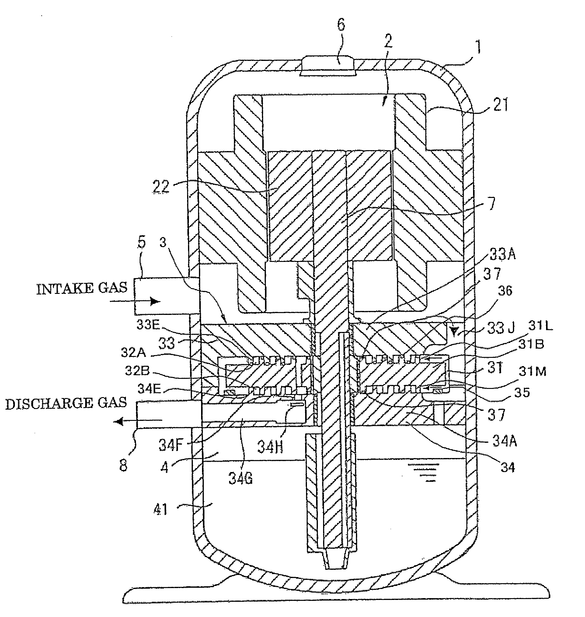
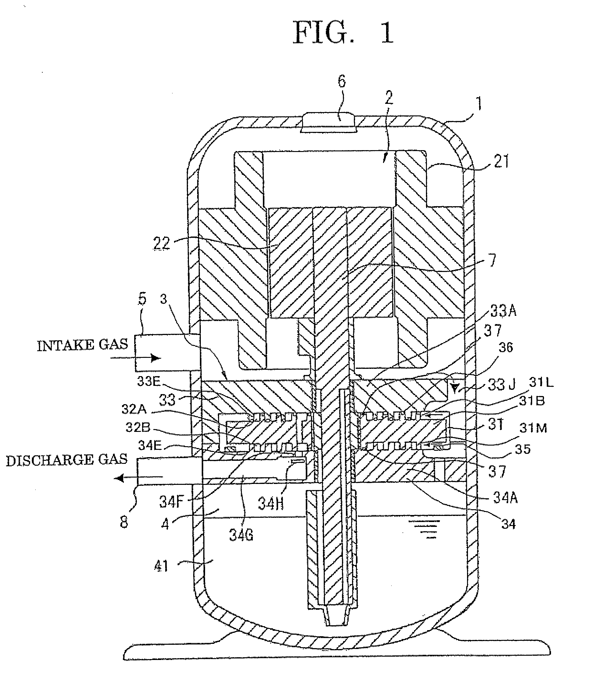
[0021]FIG. 1 is a cross section showing a configuration of a double-sided spiral scroll compressor according to Embodiment 1 of the present invention.

[0022]In FIG. 1, a motor 2 is disposed in an upper portion inside a vertical sealed vessel 1, and a compression portion 3 is disposed below the motor 2. A lubricating oil storage chamber 4 for storing lubricating oil 41 is formed further below the compression portion 3. A suction pipe 5 for sucking in gas is disposed on a side surface of the sealed vessel 1 at an intermediate portion between the motor 2 and the compression portion 3, and a discharge pipe 8 for discharging compressed gas is disposed on the compression portion 3. In addition, a glass terminal 6 for supplying electric power is disposed on an upper end of the sealed vessel 1. The motor 2 is constituted by: a stator 21 that is formed so as to have a ring shape; and a rotor 22 that is supported inside the stator 21 so as to be rotatable. A main shaft 7 is fixed to the rotor ...

embodiment 2

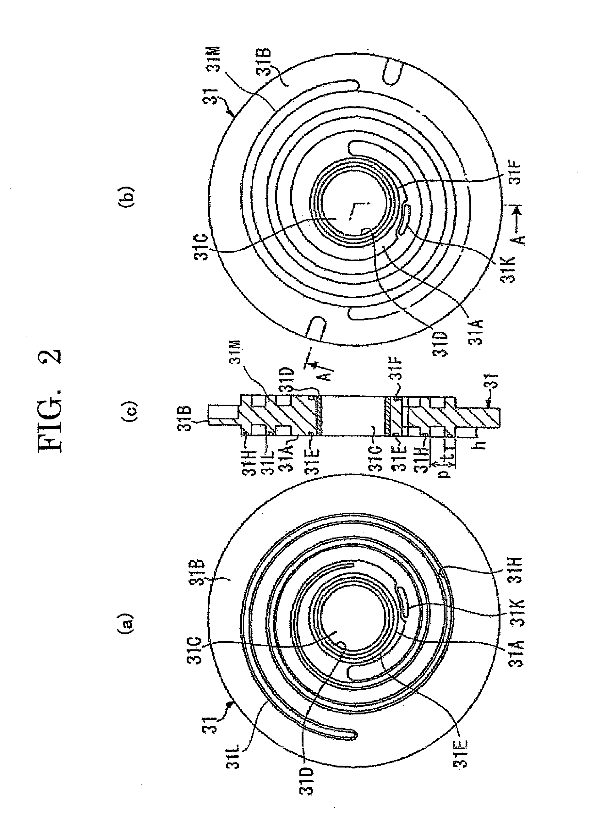
[0074]FIG. 9 is a cross section in which an orbiting scroll of a scroll compressor shown in Embodiment 2 is enlarged. In Embodiment 1, shapes of the upper spiral tooth 31L and the lower spiral tooth 31M of the orbiting scroll 31 are configured symmetrically. In Embodiment 2, number of turns n and orbiting radius r of an upper spiral tooth 31L and a lower spiral tooth 31M are made identical, and a thickness t1 of the upper spiral tooth 31L, to which a tip seal 36 is mounted, is made greater than a thickness t2 of the lower spiral tooth 31M. Here, the orbiting radius r can be expressed by Mathematical Formula 8 using thickness t and pitch p of the spiral teeth.

[Mathematical Formula 8]

[0075]r=p2-t(8)

[0076]Consequently, because the orbiting radii r of the upper spiral tooth 31L and the lower spiral tooth 31M are equal, and the thickness t1 of the upper spiral tooth 31L is greater than the thickness t2 of the lower spiral tooth 31M, the pitch p1 of the upper spiral tooth 31L is greater t...

embodiment 3

[0080]In Embodiment 1, shapes of the upper spiral tooth 31L and the lower spiral tooth 31M of the orbiting scroll 31 are configured symmetrically. In Embodiment 3, a thickness t, pitch p, and orbiting radius r of an upper spiral tooth 31L and a lower spiral tooth 31M are made identical, and the number of turns n1 in the upper spiral tooth 31L, to which a tip seal 36 is mounted, is made greater than the number of turns n2 in the lower spiral tooth 31M, to which a tip seal is not mounted.

[0081]Thickness t, height h, pitch p, and number of turns n in a spiral tooth 33E of an upper fixed scroll 33 are all equal to those of the upper spiral tooth 31L of the orbiting scroll 31, and the phase thereof is rotated by 180 degrees. Similarly, thickness t, height h, pitch p, and number of turns n in a spiral tooth 34E of a lower fixed scroll 34 are all equal to those of the upper spiral tooth 31L of the orbiting scroll 31, and the phase thereof is rotated by 180 degrees. The rest of the configur...


PUM


Abstract

The present invention provides a scroll compressor that has reduced leakage loss and high efficiency.In the present invention, an orbiting scroll 31 that has spiral teeth 31L and 31M on two surfaces, and a fixed scrolls 33 and 34 that are installed so as to face the surfaces of the orbiting scroll 31 and that have spiral teeth 33E and 34E that intermesh with the spiral teeth 31L and 31M of the orbiting scroll 31 are included, and tip seals are mounted only to a spiral tooth of the fixed scroll that intermeshes with a first spiral tooth of the orbiting scroll 31 and to the first spiral tooth of the orbiting scroll 31.

Description

TECHNICAL FIELD[0001]The present invention relates to a scroll compressor in which spiral teeth are formed on two surfaces of an orbiting scroll, and relates particularly to a technique that reduces leakage loss in a scroll compressor.BACKGROUND ART [0002]One example of a scroll compressor is a configuration constituted by: an orbiting scroll having spiral teeth formed on two sides; and a pair of fixed scrolls on which spiral teeth are formed such that the respective spiral teeth intermesh (see Patent Literature 1, for example). Hereinafter, this will be called a “double-sided spiral scroll compressor”. In double-sided spiral scroll compressors of this kind, axial thrust loads due to compressed gas cancel each other out because compression chambers are formed on both sides of the orbiting scroll.[0003]On the other hand, because there are two compression chambers in double-sided spiral scroll compressors, they have constructions in which leakage is more likely to occur from a compres...

Claims


Application Information

Patent Timeline
IPC IPC(8): F04C18/04F04C27/00
CPCF04C18/0223F04C18/0284F04C23/008F04C2210/1072F04C27/005F04C27/009F04C2210/1027F04C27/001
Inventor SEKIYA, SHINKAKUDA, MASAYUKIKODA, TOSHIHIDENAKAMURA, TOSHIYUKITOJO, KUNIOYANO, KENJISUGAWA, MASAAKIISHIZONO, FUMIHIKOSUGIHARA, MASAHIRO
Owner MITSUBISHI ELECTRIC CORP
Why Eureka
Try Eureka