Rotating piston engine

Inactive Publication Date: 2000-09-19
RAAB ANTON
View PDF8 Cites 40 Cited by
  • Summary
  • Abstract
  • Description
  • Claims
  • Application Information

AI Technical Summary

Benefits of technology

The danger of removal of the oil film by fuel condensation which occurs when a piston engine is started cold is avoided, because an oil film in the cylinder is no longer necessary. The oil-free cylinder also allows use of the engine in dusty, dry combustion air, for example in the steppes or desert, because the dust is blown through the cylinder without adhering to the cylinder wall.
The inside wall of the an

Problems solved by technology

Inherent sealing elements are unnecessary.
Any liquid and gaseous fuels can be used, resulting in low operating costs.
In reciprocating piston engines which work against top and bottom dead center of the pistons, this can lead to much higher material stress and thus to much higher maintenance costs, shorter service life of the engine

Method used


Image

  • Rotating piston engine
  • Rotating piston engine
  • Rotating piston engine

Examples


Example

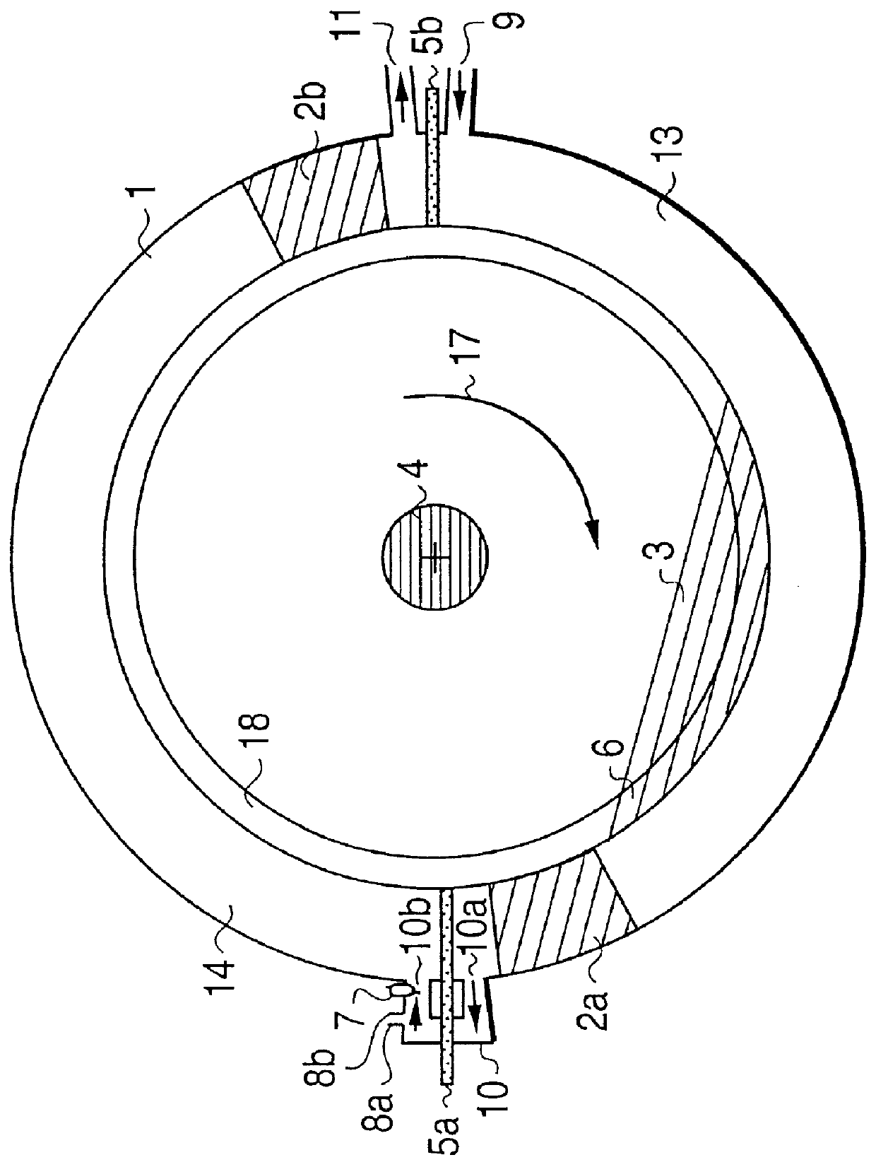
FIG. 1 shows annular cylinder 1 in which run two rotating pistons 2a, 2b which are attached to rotor disk 3. Rotor disk 3 is securely joined to driven shaft 4. Rotating pistons 2a, 2b run in direction of rotation 17 in annular cylinder 1.

In the compression phase shown in FIG. 1, rotating piston 2a has largely compressed the fresh gas in intake compression chamber 13. The fresh gas in chamber 13 is pressed against closed rotary valve 5a and via outlet line 10a into overflow channel 10. Behind rotary piston 2a new fresh gas is aspirated at the same time via intake channel 9.

Rotary valve 5a in this phase also closes annular cylinder 1.

In the direction of rotation of the pistons behind rotary valve 5a, i.e., on the side of valve 5a opposite chamber 13, the ignited gas mixture originating from the prior stroke expands and pushes rotating piston 2b in expansion chamber 14 to shortly in front of rotary valve 5b. At the same time, in front of rotating piston 2b the burned residual gases fro...


PUM


Abstract

PCT No. PCT/EP96/00193 Sec. 371 Date Jul. 18, 1997 Sec. 102(e) Date Jul. 18, 1997 PCT Filed Jan. 18, 1996 PCT Pub. No. WO96/22453 PCT Pub. Date Jul. 25, 1996An engine with one or more ring cylinders of round cross-section is disclosed. In each ring cylinder are provided at least two rotary pistons whose cross-sections match that of the ring cylinder, the pistons being mounted on the circumference of a rotary disc which is mounted on a shaft and incapable of rotating. Each cylinder is provided with disc cams in the form of rotary valves which protrude at their peripheral areas through slots which extend transversely in relation to the course of the ring cylinders. Rotary valves engage in overflow channels and in the ring cylinder between an intake compression chamber and an expansion chamber. The rotary valves engage in the ring cylinder between an expansion chamber and an intake compression chamber. The rotary valve grooves are so arranged as to clear the ring cylinder for the rotary pistons. The rotary valve recesses are so arranged as to clear the overflow channels immediately before or during closure of the aperture and during closure of the aperture by the rotary pistons.

Description

This invention relates to an engine with one or more annular cylinders with round cross section, in each annular cylinder there being at least two rotating pistons with cross sections which correspond to the cross sections of their annular cylinder.It is a rotating piston machine, with annular cylinders and pistons which rotate therein, with rotary valves as shut-off parts and stationary working walls.The invention is an internal combustion engine which belongs in the domain of rotating machinery. In it the energy is used directly to produce rotation without the intermediary of pulsating movements. In versions of the invention integrated use of cylinder walls as hydraulic and / or pneumatic pumps is possible.BACKGROUND AND SUMMARYA rotating piston machine is known (DE-38 25 354 A1) which is made with rotary valves which have the same rpm and thus necessarily a diameter roughly the same as the annular cylinders. The rotary valve fits from the outside into the annular cylinder, by which...

Claims


Application Information

Patent Timeline
IPC IPC(8): F01C3/00F01C3/02F01C1/00F01C1/356
CPCF01C1/356F01C3/02F02B2053/005
Inventor RAAB, ANTON
Owner RAAB ANTON
Why Eureka
Try Eureka