Gas diffuser ion inlet

Active Publication Date: 2014-12-04
DH TECH DEVMENT PTE
1 Cites 4 Cited by

AI-Extracted Technical Summary

Problems solved by technology

If for example, a gas jet propels the ions to be analyzed all the way to the end of the first vacuum chamber then it is difficult to efficiently focus the ions, and the se...

Benefits of technology

[0009]The present disclosure is generally directed to a gas diffuser for use in a mass spectrometer, comprising an input aperture for receiving a flow of a gas; and a gas flow conduit that extends from said input aperture to an exit aperture and is configured to provide a controlled expansion of the gas from the input aperture to the exit aperture. For example, in some embodiments, the passage of the gas through the conduit can redu...

Abstract

In some embodiments, a gas diffuser for use in a mass spectrometer is disclosed that can provide a controlled expansion of an ion-containing gas so as to reduce gas velocity for entry into subsequent stages of the mass spectrometer, e.g., a mass analyzer. In some embodiments, the controlled expansion of the gas is provided by flowing the gas through a channel whose cross-sectional area change, e.g. progressively increases, in the direction of the gas flow so as to provide controlled expansion of the gas.

Application Domain

Samples introduction/extractionDust removal +8

Technology Topic

AirflowMass analyzer +2

Image

  • Gas diffuser ion inlet
  • Gas diffuser ion inlet
  • Gas diffuser ion inlet

Examples

  • Experimental program(1)

Example

[0026]Aspects of the applicants' teachings may be further understood in light of the following description, which should not be construed as limiting the scope of applicants' teachings in any way.
[0027]This disclosure is generally directed to a gas diffuser or velocity reducer to slow the speed of a gas jet entering a vacuum chamber of a mass analyzer so that the ions carried by the gas can be more effectively focused.
[0028]In a vacuum expansion of a gas carrying ions, there is typically a need to slow the expansion speed of the gas without limiting the ion flux and without causing ion losses to walls. The latter can reduce both the sensitivity of the instrument and the precision and accuracy of the measurement.
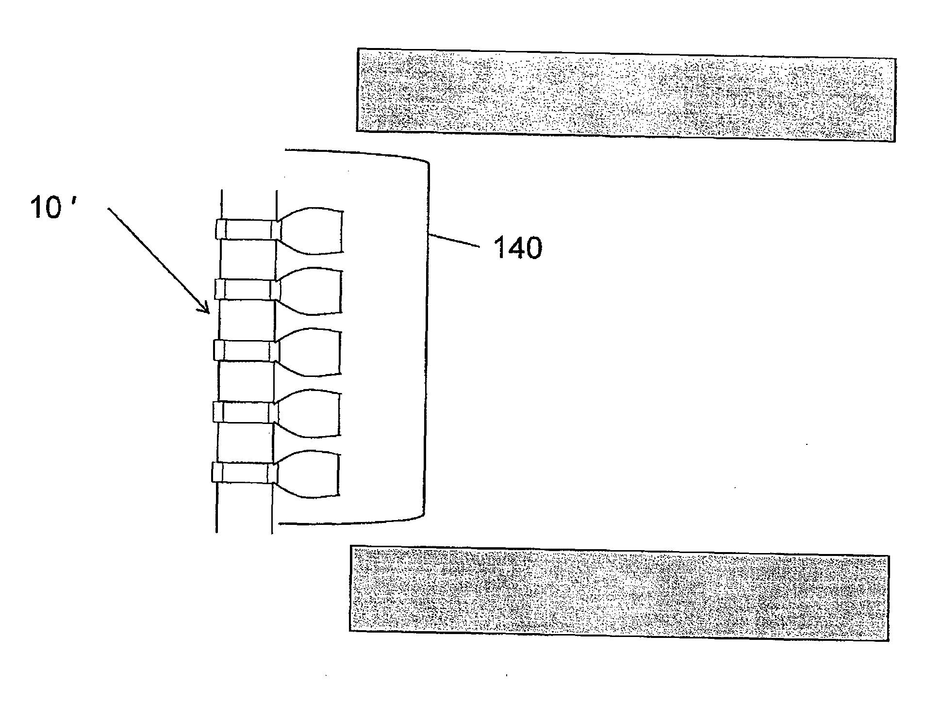
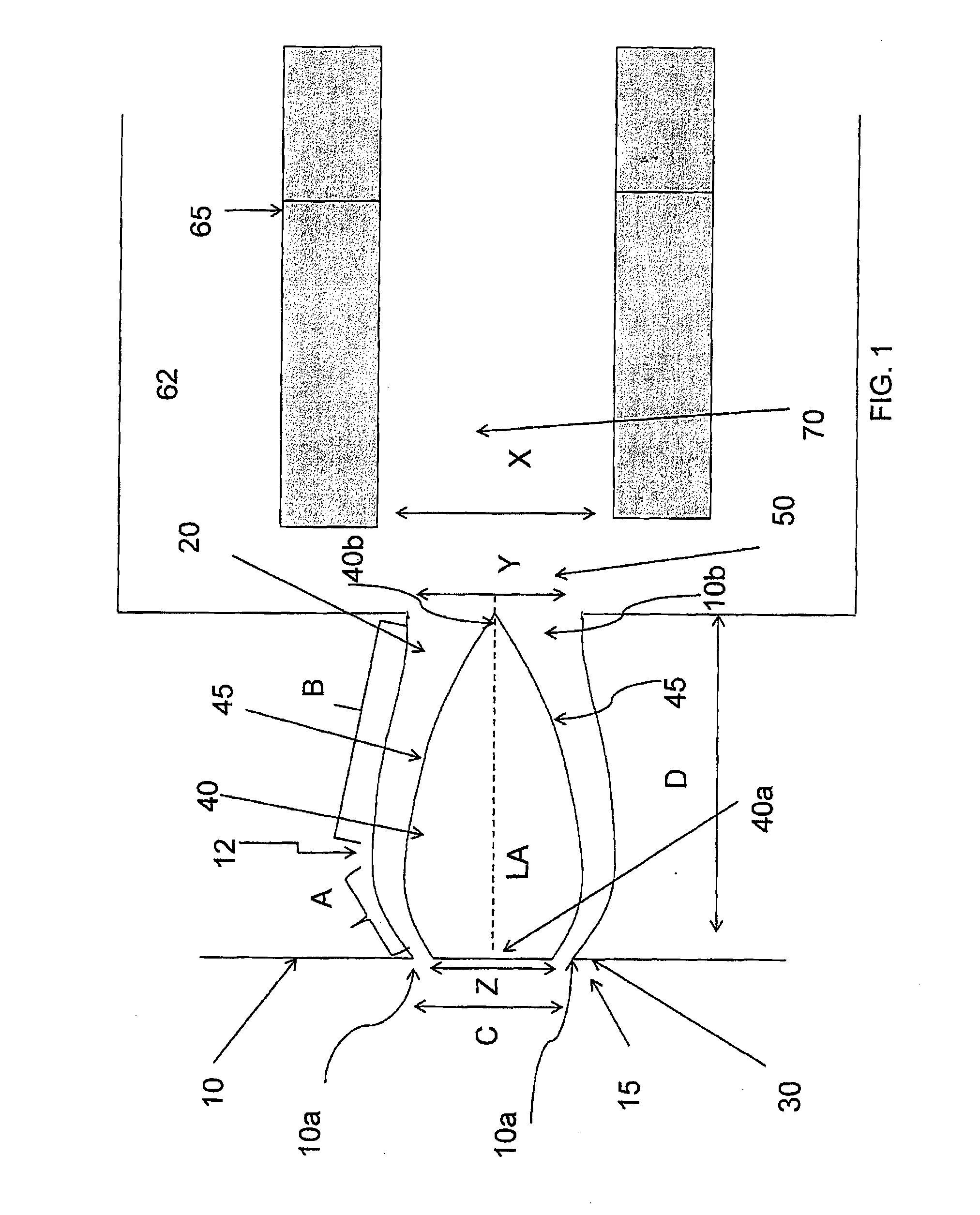
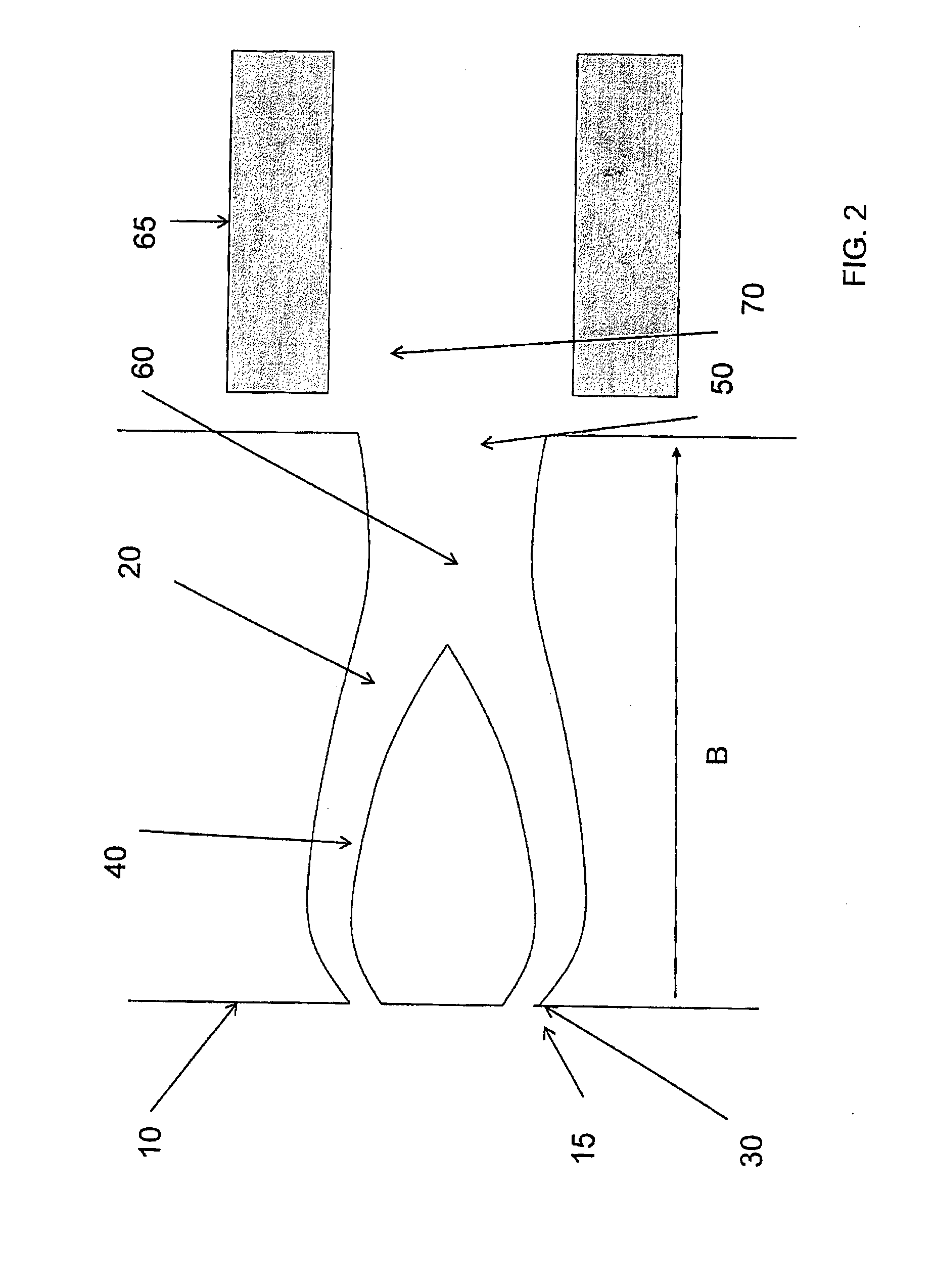
[0029]In some embodiments, as shown in FIG. 1, a gas diffuser 10 can comprise an annular input aperture 10a that allows entry of an ion containing gas into a channel or conduit 15 that is formed between an outer curved wall 30 and a solid core 40, which provides an inner curved wall 45 of the conduit. In this illustrative embodiment, the solid core 40 extends from a proximal surface 40a to a distal tip 40b. As discussed below, the conduit 15 allows for controlled expansion of the gas as it flows from the input aperture 10a to an exit aperture 10b, thereby providing controlled reduction of the gas velocity.
[0030]In the instant embodiment, the channel 15 comprises a first gas flow region A that extends from the input aperture 10a to an inflection section 12. In this illustrative embodiment, in the first gas flow region A, the outer wall 30 and the inner wall 45 of the channel 15 diverge away from a longitudinal axis (LA) of the gas diffuser along a direction away from the input aperture. The channel 15 further comprises a second region B that extends from the inflection section 12 to the output aperture 10b. In this illustrative embodiment, in the second gas flow region, the outer wall 30 and the inner wall 45 converge toward the longitudinal axis (LA) along a direction toward the output aperture, though at different rates. In this illustrative embodiment, in both regions, the cross-sectional area of the channel progressively increases in a direction from the input aperture to the output aperture with a greater rate of increase in the second region B.
[0031]In some embodiments, the first gas flow region can be a substantially annular channel. In some such embodiments, the first gas flow region can comprise a channel having a substantially uniform cross-sectional area over its length.
[0032]The gas introduced into the gas diffuser via the input aperture 10a first expands within the first gas flow region and then further expands in the second gas flow region of the conduit 15, where the expansion in the second region is more rapid than that in the first region. The combined expansion of the gas in the first and second channel regions results in a controlled reduction of the gas velocity. As the gas flows through the channel, it can maintain contact with the inner and outer walls 30 and 45 (e.g., due to Coanda effect (attraction of a moving fluid toward a solid wall or surface))—that is, the boundary layers of the gas flow remain in contact with the walls. The ion-containing gas exiting the gas diffuser through the output aperture 10b enters a first vacuum chamber 62 of a mass analyzer that is disposed downstream from the gas diffuser. In this illustrative embodiment, the vacuum chamber contains an RF (radio frequency) ion guide 65 to capture and focus the ions into a second vacuum chamber. The RF ion guide can be an RF multipole or an RF ring guide or an RF or DC ion funnel.
[0033]Although typical sizes and distances can vary, the cross section of the inner solid core at the portion of the gas diffuser where the gas enters the diffuser (Z) is typically in a range of about 1.8 mm to about 8 mm, e.g., about 4.6 mm. The annular ring typically has a diameter (C) of between about 2 and about 10 mm and is often about 5 mm. The output aperture 10b where the gas jet exits the diffuser has generally a circular shape with a diameter (Y) in a range of about 2 to about 10 mm, and in various embodiments, a diameter greater than the diameter of the annular ring. In some embodiments, the diameter of output aperture 10b where the gas jet exits is about 8 mm. The gas diffuser can have a variety of thicknesses commensurate with the other dimensions. In one example the diffuser has a thickness (D) (a size along the longitudinal axis (LA)) that ranges between about 2 and about 10 mm and in some embodiments is about 10 mm.
[0034]In some cases the outer wall 30 can extend beyond distal end of the solid core to avoid a sudden re-expansion of the gas into a subsequent vacuum chamber. For example, as shown in FIG. 2, the extension of the outer wall of the channel beyond the distal end of the solid core can result in a long channel 60 proceeding towards the exit aperture 50. Again dimensions may vary, but in some embodiments, the thickness of the diffuser (B) can range from about 5 to about 20 mm. It should be noted that the continuation of the outer walls past the solid inner core will also vary in distance but in some embodiments that comprise such an extension of the channel, the length of the channel between the distal end of the sold inner core and the output aperture 10b can be typically about 30-100% of the thickness of the solid inner core.
[0035]The gas diffuser can be used as the first aperture into an ion guide 65 located in vacuum chamber 62 of a mass spectrometer analyzer. The dimensions of the ion guide can be selected to match the diameter of the gas and ion beam exiting from the diffuser. In this illustrative embodiment, the ion guide can have a substantially circular input aperture with a diameter (X) of between about 4 and about 20 mm. In some embodiments, the diameter (X) can be about 15 mm. Typically the ratio of the diameter (X) of the ion guide 65 relative to the diameter (Y) of the output aperture of the gas diffuser can be between about 1 to about 1.5 and in some embodiments in a range about 1 to 2.
[0036]Generally, the pressure in the vacuum chamber 62 can be between about 1 Torr and about 30 Torr (wherein approximately 760 Torr is atmospheric pressure). In some embodiments, the vacuum chamber 62 can comprise an ion focusing device 65, such as an RF ion guide, e.g., an RF multipole (e.g., RF quadrupole, hexapole or octapole) or an RF ring guide or ion tunnel or ion funnel. Other RF containment or focusing devices can also be used.
[0037]In some embodiments, the gas diffuser 10 can be formed without the solid inner element. For example, in some such embodiments, the gas expansion and velocity can be controlled by the surface shape of the outer wall 90, e.g., as shown in FIG. 3. In this illustrative embodiment, the wall 90 is curved and flares out from an input aperture 10a to an output aperture 10b, thereby providing an inner volume with a progressively increasing cross-section from the input aperture to the output aperture for facilitating controlled expansion of the gas. In this illustrative embodiment, the wall 90 is positioned within an outer boundary that would be formed by a free jet expansion 100 (the shape and size of which is well known, according to the orifice diameter and the pressure in the chamber) through the input aperture (i.e., a gas expansion through the input aperture in absence of the wall 90).
[0038]In some embodiments, a gas diffuser 10′ can comprise multiple gas diffusing elements 140 that can be used to form small localized jets, each jet having a small diameter relative to the area defined by the distribution of the jets on the diffuser as shown in FIGS. 4A and 4B. The gas diffusing elements can be implemented in a variety of ways. In some embodiments, the gas diffusing elements can be in the form of an array of apertures (holes) that can have a net effect of reducing the gas velocity. In some embodiments, the gas diffusing elements can be implemented as those discussed above in the preceding embodiments and shown in FIGS. 1-3. In some embodiments, the use of multiple small gas jets can prevent the formation of a large axial gas flow rate along the axis while still allowing a large number of ions to enter a downstream vacuum chamber. If the gas diffusing elements are spaced apart sufficiently then the barrel shock wave formed by the gas flow as the gas exits the exit aperture of a gas diffusing element does not interact with a respective shock wave associated with an adjacent aperture. In this manner, the gas expansion through each of the apertures can be independent from that through the other apertures, resulting in a momentum from each gas jet through each aperture that is relatively small. In some embodiments, each aperture or channel can be formed like the gas diffuser depicted in FIG. 3 with suitable dimension. For example, each of at least ten apertures can have a diameter of about 0.25 mm and each barrel shock may be no more than 3 mm in diameter at a given pressure of the incoming gas jet. Consequently, in some such embodiments, the apertures would be spaced apart by at least 1.5 mm. The apertures can be arranged so that they are disposed relative to one another in any desired pattern, e.g., any two-dimensional pattern within an area, including a line, a circle or a random pattern. An RF Ion guide that is larger in cross-sectional area than the cross-sectional area of the pattern of apertures or channels can be used to contain and focus the ions exiting the apertures of the multiple gas diffusing elements. By way of non-limiting example, an RF ring guide or an RF multipole having an inner diameter of about 10 mm can be used.
[0039]In some embodiments, a gas diffuser 10′ according to the applicants' teachings can comprise a porous membrane 150 located at the end of a channel 160 as shown in FIG. 5. Ions enter the channel 160 via an input aperture 10″a and exit the channel through the porous membrane 150. The porous membrane can comprise a porous glass or a porous metal such as stainless steel frit, or a metal plug containing many small channels. The size, diameters and numbers of holes in the plug can be adjusted to provide the required gas flow into the vacuum system, and can be obtained by routine experimentation. In some embodiments, the porous membrane can be about 5 mm thick, containing channels that are about 0.1 mm in diameter or less. In some embodiments, the channel 160 can be cylindrical, although not necessarily so. The channel 160 can be of varying widths and lengths. In some embodiments, it can have a width (Y) (diameter if cylindrical) of between about 0.5 to about 2 mm, and a length (L) of between about 5 to about 20 mm. This embodiment can improve the contact time between the gas and the channel's wall, thus helping heat transfer between the gas and the wall. In some embodiments the channel and porous membrane can be heated to improve desolvation, and to reduce adsorption of organic contamination materials to the walls. In some embodiments, the porous membrane can inhibit the entry of contaminants, such as particles, in the gas, if any, into subsequent stages which could otherwise contaminate the surfaces and cause ion loss.
[0040]In some embodiments, a gas diffuser 10′″ comprises both an expansion region 170 followed by a compression region 180 as shown in FIG. 6. The expansion region can allow the gas to expand beyond the desired beam diameter, slowing the gas stream to a low velocity and then the flow can be recompressed to the desired diameter for the beam. In some embodiments, such expansion followed by compression can ensure that the resultant gas flow is relatively homogeneous and the momentum from the gas expansion has already been dissipated. As shown in FIG. 6, the gas diffuser 10′″ can comprise a channel 201 that receives a flow of gas through an inlet orifice 200. In this illustrative embodiment, the channel 201 flares out from the orifice 200 to an inflection section 220 beyond which the channel gradually narrows to reach an exit orifice 210, thereby providing a controlled expansion and compression of the ion-containing entering gas.
[0041]In some embodiments, the diameter (A) of the gas inlet orifice 200 can be between about 1 mm and about 2 mm and the gas exit 210 diameter (Y) can be between 4 and 10 mm, e.g., to match the diameter of the RF ion guide. At its widest point (Z) the diffuser, in some embodiments, can have a size in a range between about 40 and about 20 mm. In some embodiments, the gas diffuser 10″′ can have a thickness of between about 5 and about 20 mm.
[0042]By way of example, if the gas flows through the 2 mm orifice into vacuum at a rate of 0.5 Liters/sec (L/s), the gas velocity at a pressure of 5 Torr with a cross-sectional diameter of 4 mm is 100 m/sec which is far less than the sonic velocity of 436 msec.
[0043]In various embodiments, the use of a gas diffuser according to the present teachings in a mass spectrometer can provide a higher sensitivity by allowing the use of larger entrance apertures without compromising the ability of the spectrometer to focus ions efficiently.
[0044]The section headings used herein are for organizational purposes only and are not to be construed as limiting the subject matter described in any way. While the applicant's teachings are described in conjunction with various embodiments, it is not intended that the applicant's teachings be limited to such embodiments. On the contrary, the applicant's teachings encompass various alternatives, modifications, and equivalents, as will be appreciated by those of skill in the art.

PUM

no PUM

Description & Claims & Application Information

We can also present the details of the Description, Claims and Application information to help users get a comprehensive understanding of the technical details of the patent, such as background art, summary of invention, brief description of drawings, description of embodiments, and other original content. On the other hand, users can also determine the specific scope of protection of the technology through the list of claims; as well as understand the changes in the life cycle of the technology with the presentation of the patent timeline. Login to view more.

Similar technology patents

Armature for a solenoid actuator

ActiveUS20110110804A1increase cross-sectional area
Owner:DELPHI TECH IP LTD

Rotating piston engine

InactiveUS6119649Aleakage loss be reducereduce velocity of gas
Owner:RAAB ANTON

Classifier and a method of modifying a classifier for use with a pulveriser

InactiveUS20140151478A1increase cross-sectional area
Owner:COAL MILLING PROJECTS (PTY) LTD

Premixed Fuel Nozzle

ActiveUS20200173662A1increase cross-sectional areadecrease cross-sectional area
Owner:GENERAL ELECTRIC CO

Method of forming T- or gamma-shaped electrode

InactiveUS20080124852A1improved step coverageincrease cross-sectional area
Owner:ELECTRONICS & TELECOMM RES INST

Surface cleaning apparatus

ActiveUS20200022547A1reduce backpressureincrease cross-sectional area
Owner:OMACHRON INTPROP

Classification and recommendation of technical efficacy words

  • reduce velocity of gas
  • increase cross-sectional area

Rotating piston engine

InactiveUS6119649Aleakage loss be reducereduce velocity of gas
Owner:RAAB ANTON

Display device

ActiveUS20110162831A1increase cross-sectional area
Owner:SAMSUNG ELECTRONICS CO LTD +1

Detachable insert-type cutting tool

ActiveUS20100178117A1increase cross-sectional areaproduction cost be reduce
Owner:MITSUBISHI MATERIALS CORP

Crane boom with multi main-chord

InactiveUS20110284490A1structural carry capacity be improveincrease cross-sectional area
Owner:SHANGHAI SANY TECH

Method of forming T- or gamma-shaped electrode

InactiveUS20080124852A1improved step coverageincrease cross-sectional area
Owner:ELECTRONICS & TELECOMM RES INST

Premixed Fuel Nozzle

ActiveUS20200173662A1increase cross-sectional areadecrease cross-sectional area
Owner:GENERAL ELECTRIC CO
Why Eureka
Try Eureka