Air Blowing Arrangement For a Combined Refrigerator

a combined refrigerator and air blowing technology, which is applied in the direction of domestic cooling apparatus, lighting and heating apparatus, and cooling fluid circulation, etc., can solve the problems of reducing the esthetic characteristics of the combined refrigerator, and reducing the cost of assembling, so as to achieve the effect of simple assembling and cost reduction

Inactive Publication Date: 2008-08-21
WHIRPOOL SA
View PDF3 Cites 43 Cited by
  • Summary
  • Abstract
  • Description
  • Claims
  • Application Information

AI Technical Summary

Benefits of technology

[0010]By reason of the inconveniences presented by the solutions known so far, it is an objective of the present invention to provide an air blowing arrangement for a combined refrigerator of the type considered above, presenting a construction which is simple to assemble and of relatively reduced cost, and which can be applied to different models of refrigerator.
[0011]It is a further objective of the present invention to provide an air blowing arrangement, which requires a finishing element of reduced dimensions and which interferes very little with the esthetic design of the interior of the refrigerating compartment of the combined appliance.

Problems solved by technology

This known construction requires the provision of a finishing cover to cover the whole extension of the diffusing duct, with the consequent costs in material and investments in moulds with considerably dimensions.
In addition to the inconvenience above, this prior art construction requires special cares for assembling the diffusing duct and its finishing cover, turning the assembling operations difficult and expensive and requiring a design for both the diffusing duct and the finishing cover for each model of combined refrigerator.
Finally, the fact of the diffusing duct-finishing cover assembly being exposed inside the refrigerating compartment restricts or impairs the introduction of new esthetic characteristics in the combined refrigerator.

Method used


Image

  • Air Blowing Arrangement For a Combined Refrigerator
  • Air Blowing Arrangement For a Combined Refrigerator
  • Air Blowing Arrangement For a Combined Refrigerator

Examples


Embodiment Construction

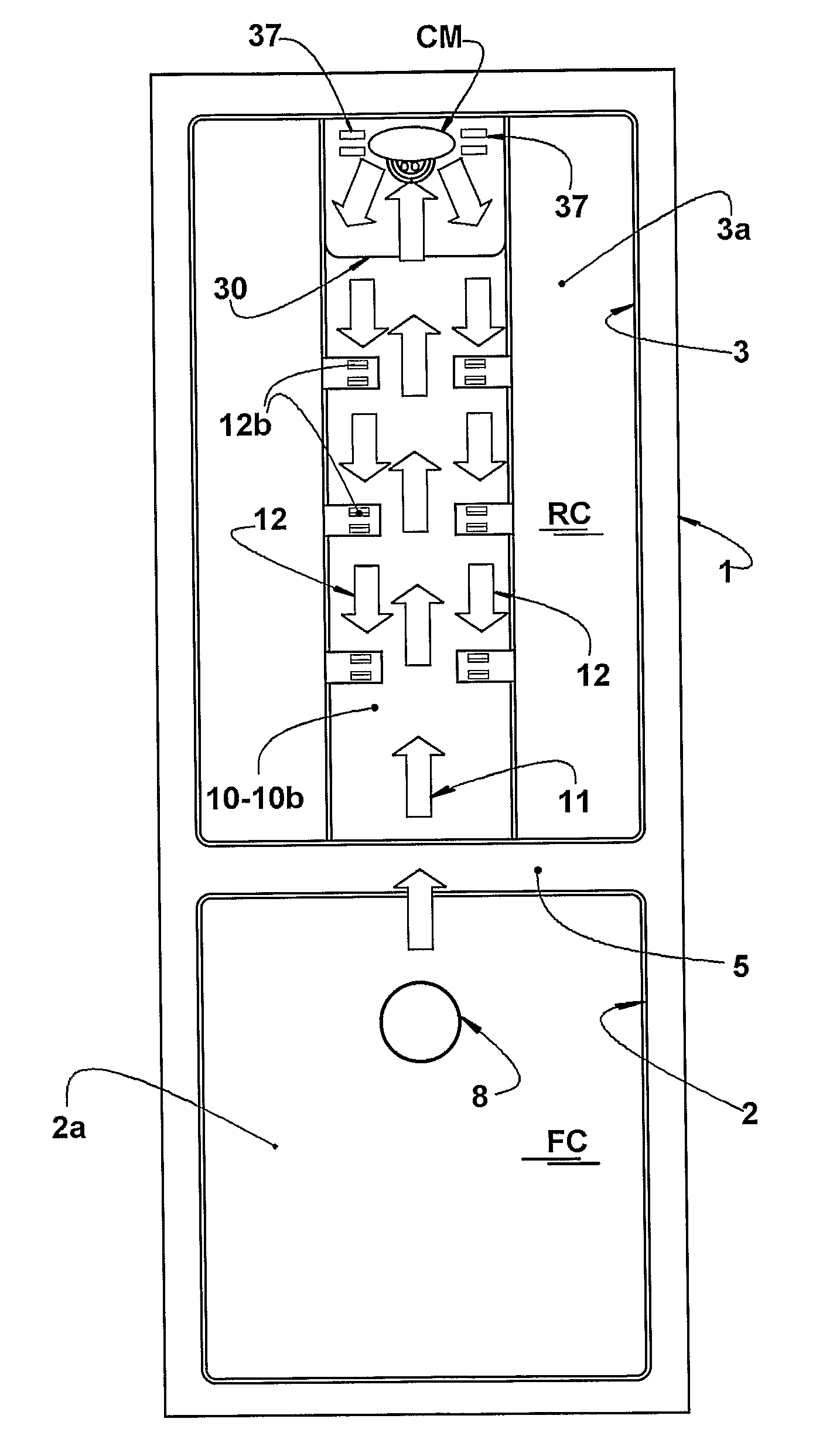
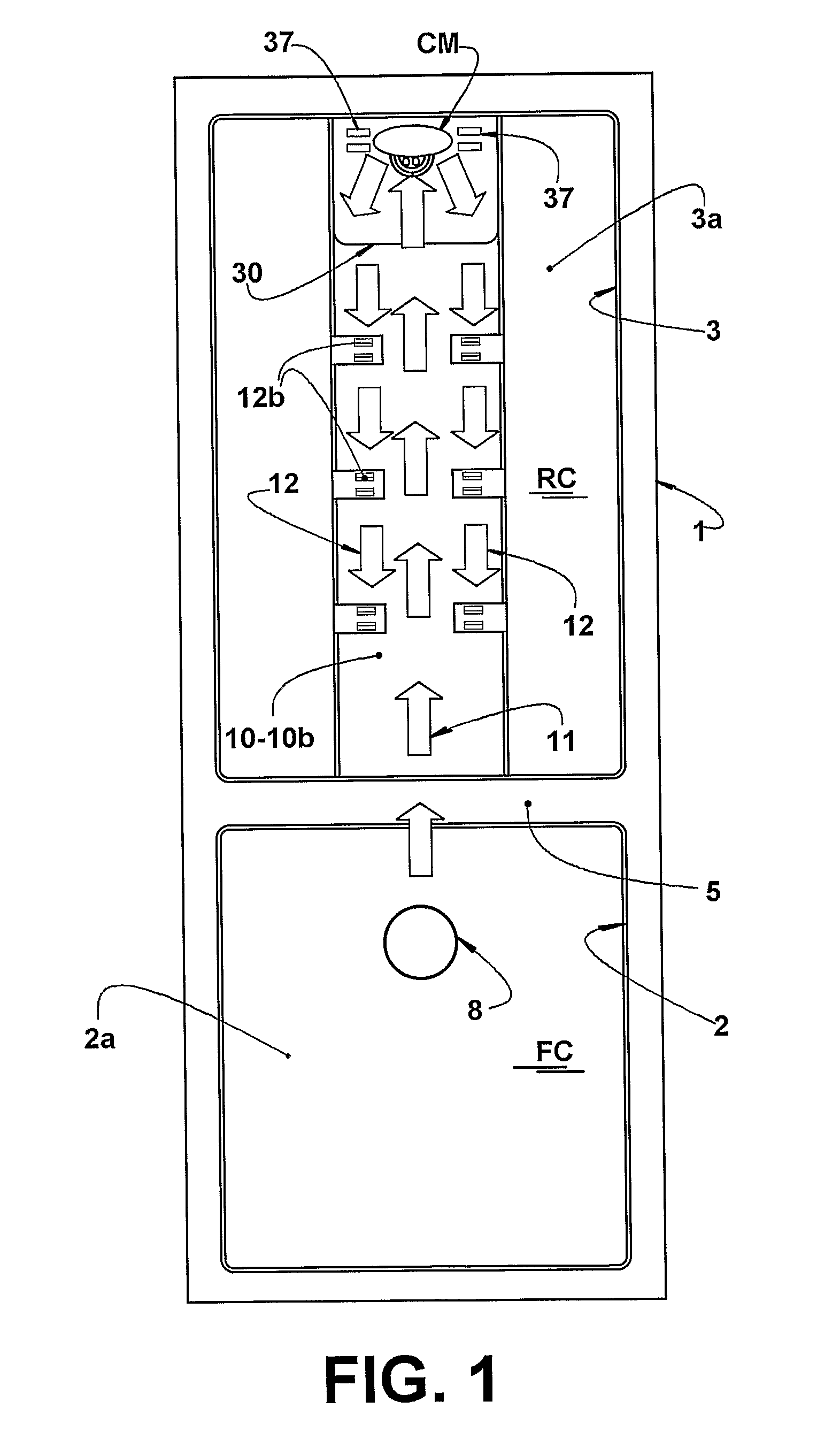
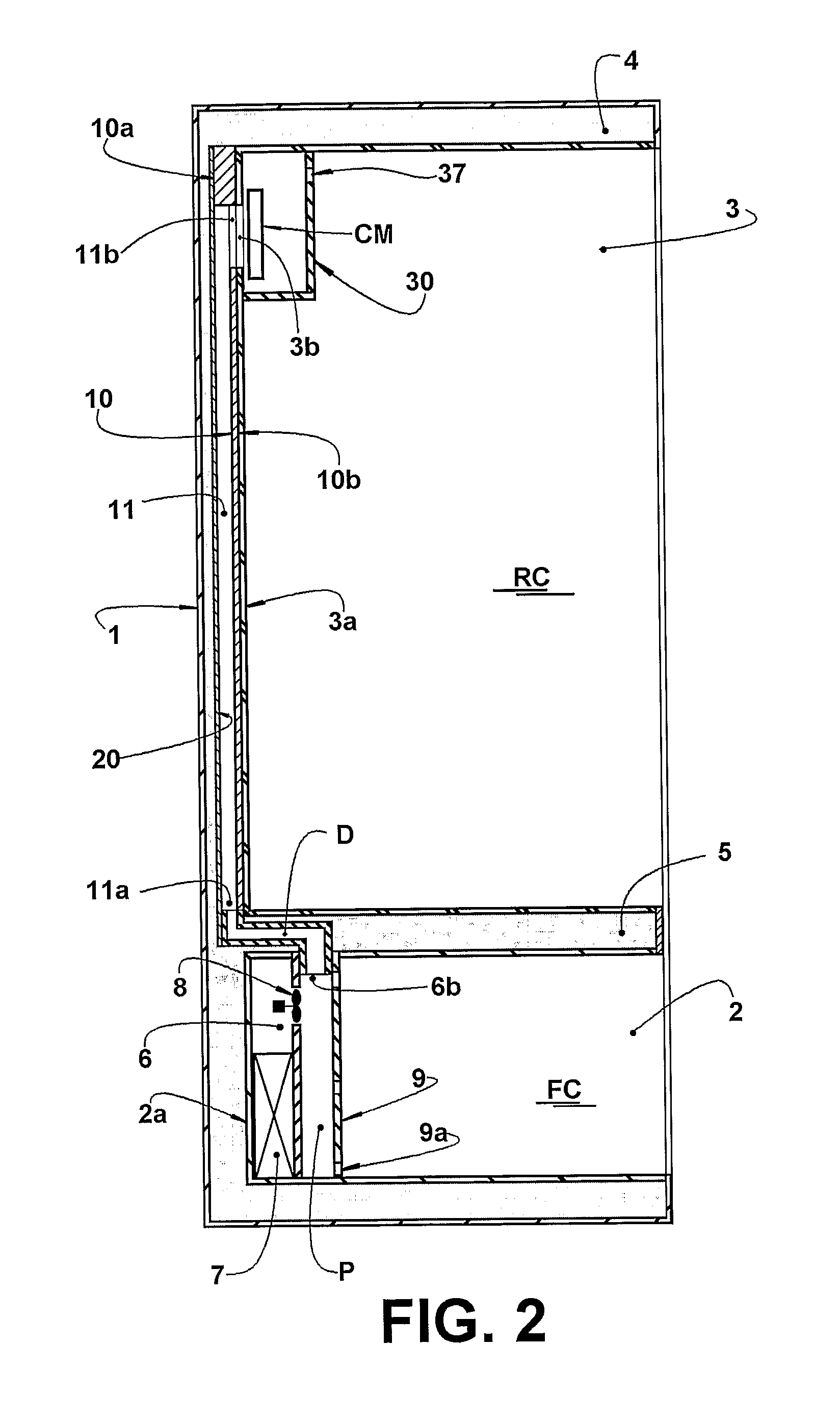
[0031]As already mentioned, the present air blowing arrangement can be applied to the combined refrigerators of the no frost type and with forced ventilation, presenting the freezing compartment FC disposed above or under the refrigerating compartment RC.

[0032]FIGS. 1-5 illustrates a combined refrigerator of the type considered herein and in which the freezing compartment FC is disposed under the refrigerating compartment RC. In these exemplary applications, the refrigerator comprises a cabinet defined by an outer case 1 generally made of metallic sheet, an inferiorly disposed inner case 2, defining the freezing compartment FC, and a superiorly disposed inner case 3, defining the refrigerating compartment RC. The two inner cases 2, 3 are separated from each other and also from the outer case 1 by a thermal insulating filler 4, generally made of injected and expanded polyurethane (foam), said thermal insulating filler 4 further defining a dividing wall 5 horizontally lying between th...


PUM


Abstract

An air blowing arrangement for a combined refrigerator of the forced ventilation type and that comprises: a cabinet formed by an outer case and by two inner cases spaced from each other by a thermal insulating filler and defining a freezing compartment and a refrigerating compartment; and an air diffusing element defining at least one air distributing duct, having an air inlet in communication with the interior of the inner case of the freezing compartment and a plurality of air outlets opened to the interior of the refrigerating compartment. The air diffusing element is disposed in the interior of the thermal insulating filler and seated against the rear wall of the inner case of the refrigerating compartment, said rear wall being provided with a plurality of windows aligned with respective air inlet openings of the air distributing duct.

Description

FIELD OF THE INVENTION[0001]The present invention refers to an air blowing arrangement to be applied to a combined refrigerator of the forced ventilation type and presenting a single cabinet that internally defines a freezing compartment and a refrigerating compartment, usually separated by a horizontal dividing wall.PRIOR ART[0002]The combined refrigerators are generally constituted by a cabinet formed of an outer case, usually in metallic sheet, and by two inner cases molded in plastic material, EPS for example, which are spaced from each other and also from the outer case by a thermal insulating filler generally in polyurethane foam injected between said outer case and inner cases. The inner cases respectively define the freezing compartment and the refrigerating compartment, and the freezing compartment can be disposed above or below the refrigerating compartment and separated therefrom by the dividing wall.[0003]These combined refrigerators with forced ventilation are provided ...

Claims


Application Information

Patent Timeline
Patent Type & Authority Applications(United States)
IPC IPC(8): F25D17/06F25D11/02F25D17/00F25B49/00
CPCF25D17/065F25D23/061F25D23/068F25D2317/0682F25D2317/067F25D2317/0672F25D2317/0666
Inventor FERREIRA, LUIZ AFRANIO ALVESMEZAVILA, MOACYR MARANGONECARGNIN, ADRIANOIGNACIO JR, LAURO FERNANDO SOUZA
Owner WHIRPOOL SA
Why Eureka
Try Eureka