
Real-image variable magnification finder optical system and imaging apparatus

a variable magnification finder and optical system technology, applied in the field of real-image variable magnification finder optical system and imaging apparatus, can solve the problems of difficult to make satisfactory compensation, increase in cost, degradation of performance, etc., and achieve satisfactory optical performance.

Inactive Publication Date: 2008-08-21
SONY CORP
View PDF4 Cites 8 Cited by
  • Summary
  • Abstract
  • Description
  • Claims
  • Application Information

AI Technical Summary

Benefits of technology

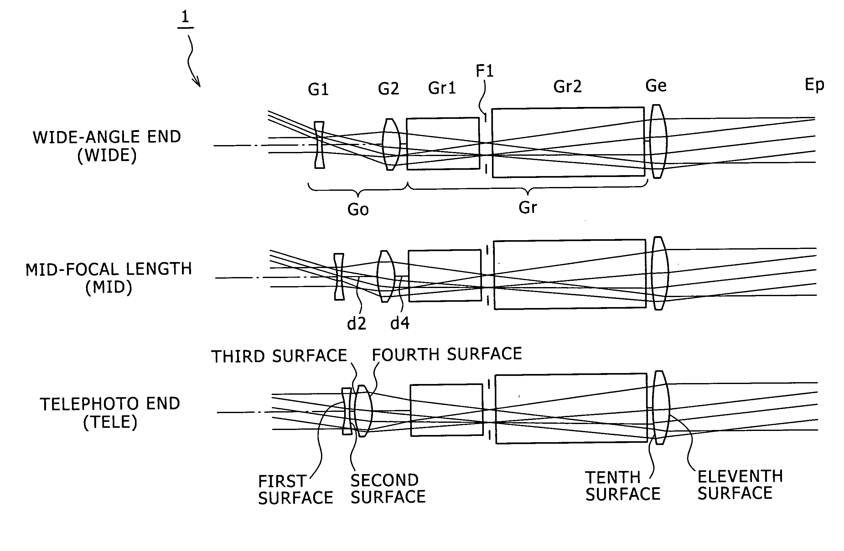
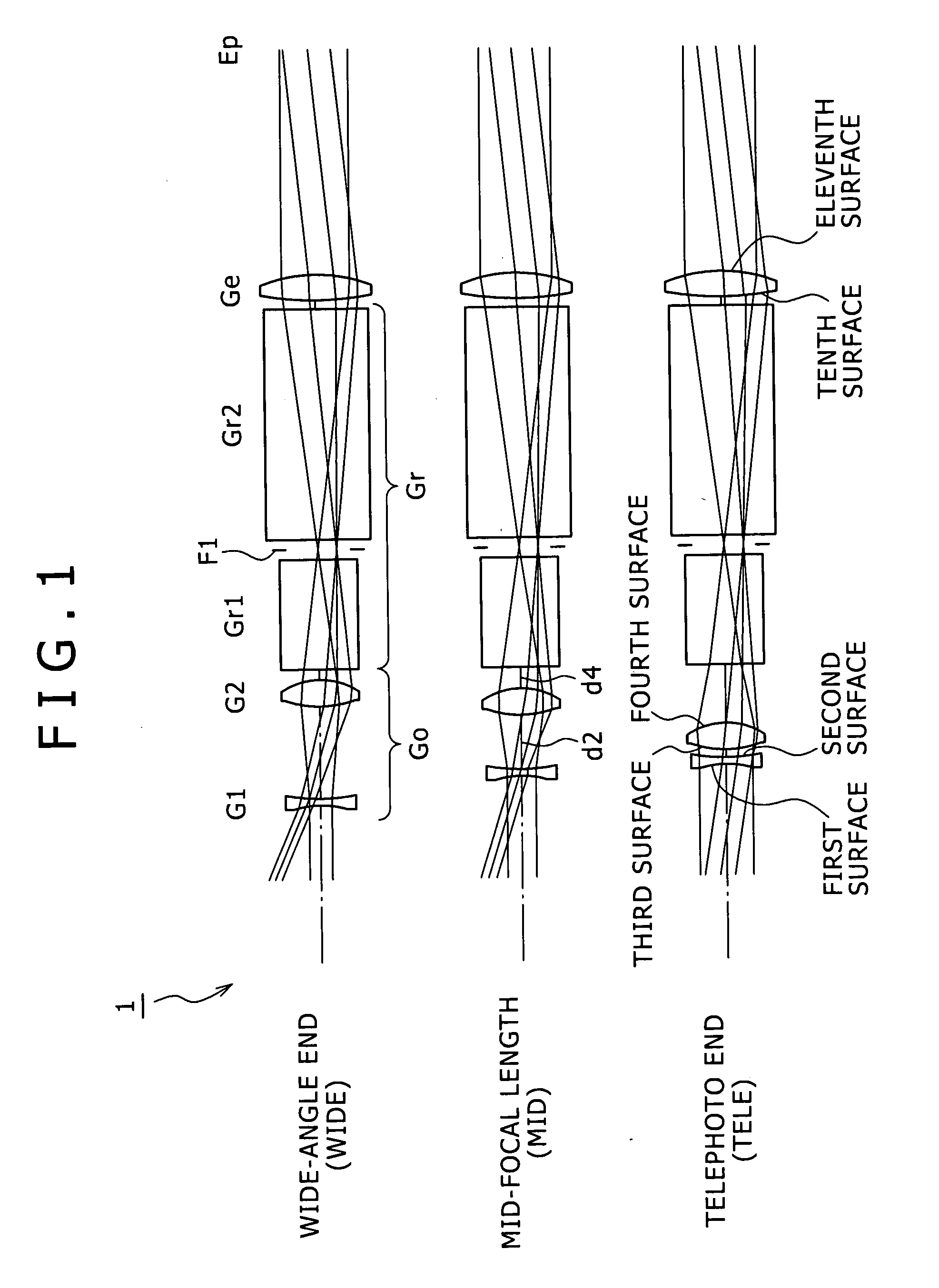
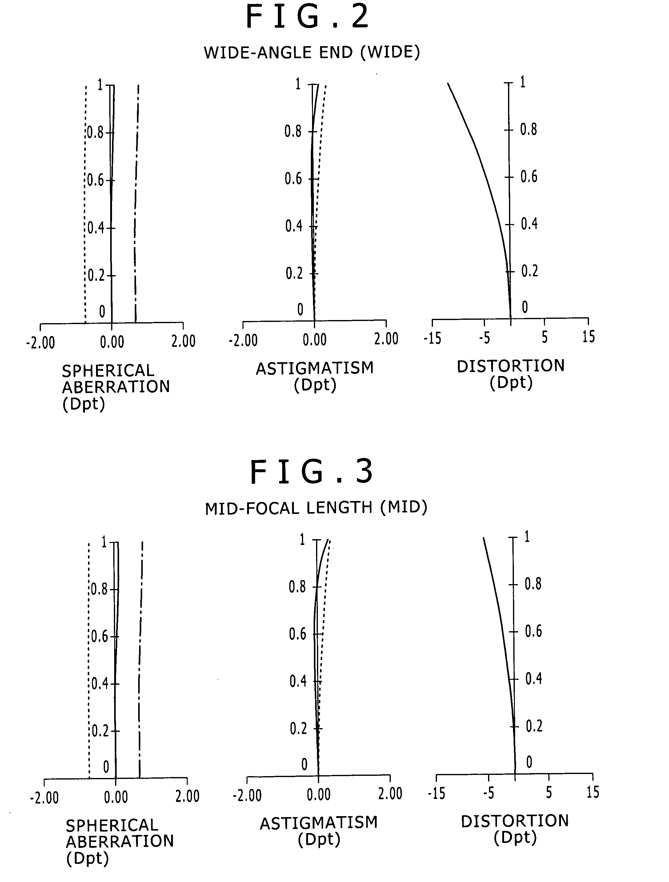
[0008]The present invention addresses the above-identified circumstances to provide: (1) a real-image variable magnification finder optical system that realizes a miniaturized configuration, and at the same time, has satisfactory optical performances, particularly, ensuring that a diopter deviation is hard to occur; and (2) an imaging apparatus equipped with the real-image variable magnification finder optical system.
[0011]According to embodiments of the present invention, it is possible to prevent the occurrence of a diopter difference and accomplish miniaturization together with satisfactory optical performances.

Problems solved by technology

However, it is quite difficult to make satisfactory compensation for various types of aberrations occurring in each lens group, while maintaining a predetermined variable magnification ratio.
In addition, a diopter deviation supposed to be the main cause of a degradation of performance occurs depending on component tolerances or variations occurring at the time of lens incorporation.
Thus, modification such as those for improvement in a component accuracy and additional installation of an adjusting mechanism become required, thereby resulting in a cost increase.

Method used


Image

  • Real-image variable magnification finder optical system and imaging apparatus
  • Real-image variable magnification finder optical system and imaging apparatus
  • Real-image variable magnification finder optical system and imaging apparatus

Examples


Embodiment Construction

[0017]Hereinafter, embodiments of a real-image variable magnification finder optical system and an imaging apparatus according to embodiments of the present invention are described with reference to drawings.

[0018]Firstly, the real-image variable magnification finder optical system of one embodiment of the present invention is described.

[0019]The real-image variable magnification finder optical system of an embodiment of the present invention includes, in the order from an object side, an objective lens group having a positive refractive power, a member (such as a prism and a mirror) for forming an erect image from an image inverted by the objective lens group, and an eyepiece having a positive refractive power. The objective lens group includes, in positions in the order from the side of the object, a first lens group having a negative refractive power and a second lens group having a positive refractive power to perform zooming and compensate a dioper change caused by zooming by m...


PUM


Abstract

A real-image variable magnification finder optical system includes, in the order from an object side, an objective lens group having a positive refractive power, a member for forming an erect image from an image inverted by the objective lens group, and an eyepiece lens having positive refractive power. The objective lens group includes, in the order from an object side, a first lens group having a negative refractive power and a second lens group having positive refractive power to perform zooming and compensate a diopter change caused by the zooming by moving the first lens group and the second lens group in an optical axis direction. The objective lens satisfies a predetermined condition.

Description

BACKGROUND OF THE INVENTION[0001]1. Field of the Invention[0002]The present invention relates to a novel real-image variable magnification finder optical system and an imaging apparatus. More particularly, it relates to a small-sized, satisfactory-optical performance real-image variable magnification finder optical system suitable for mounting to cameras such as digital still cameras, as well as to an imaging apparatus equipped with the real-image variable magnification finder optical system.[0003]2. Description of Related Art[0004]In a camera composed of a photo-taking optical system having a zooming function and a real-image finder optical system that are configured as separate systems, a zooming function adaptable to variations in a shooting angle of view has been also provided to the real-image finder optical system. As such a finder optical system, various types of real-image variable magnification finders ensuring satisfactory appearance of a field frame have been proposed.[00...

Claims


Application Information

Patent Timeline
Patent Type & Authority Applications(United States)
IPC IPC(8): G02B15/14
CPCG02B15/163G02B15/1425
Inventor FUJIHARA, KATSUYA
Owner SONY CORP
Learn More