
Developing device, process cartridge, and image forming apparatus

Active Publication Date: 2008-08-21
RICOH KK
View PDF4 Cites 19 Cited by
  • Summary
  • Abstract
  • Description
  • Claims
  • Application Information

AI Technical Summary

Benefits of technology

[0014]The present invention provides a developing device, a process cartridge, and an image forming apparatus in which one or more of the above-described disadvantages are eliminated.
[0015]A preferred embodiment of the present invention provides a developing device, a process cartridge, and an image forming apparatus in which the amount of scattered toner is small even when plural developer conveying units are provided.
[0017]According to one embodiment of the present invention, a developing device, a process cartridge, and an image forming apparatus are provided, in which the amount of scattered toner is small even when plural developer conveying units are provided, because a ventilation unit is provided for performing ventilation between a developer conveying unit whose internal pressure increases and a developer conveying unit whose internal pressure decreases.

Problems solved by technology

The problem with the developing device disclosed in patent document 1 is that the toner scatters outside the developing device and soils the inside of the image forming apparatus, and the scattered toner soils the output image.

Method used


Image

  • Developing device, process cartridge, and image forming apparatus
  • Developing device, process cartridge, and image forming apparatus
  • Developing device, process cartridge, and image forming apparatus

Examples


first embodiment

[0029]A first embodiment of the present invention is described in detail with reference to FIGS. 1 through 7.

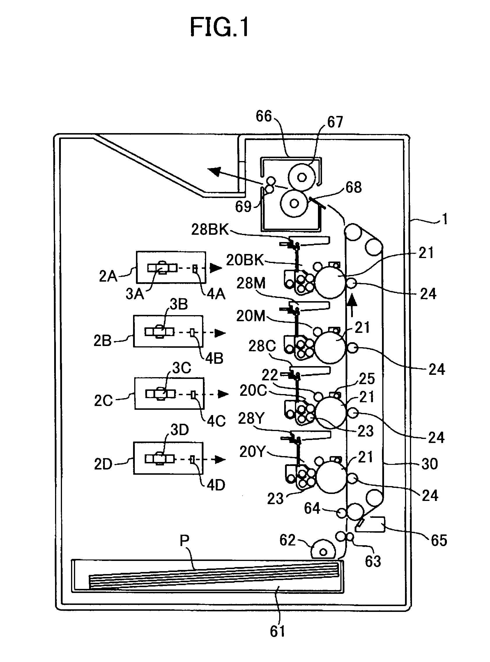
[0030]The overall configuration and operations of an image forming apparatus according to the first embodiment are described with reference to FIG. 1.

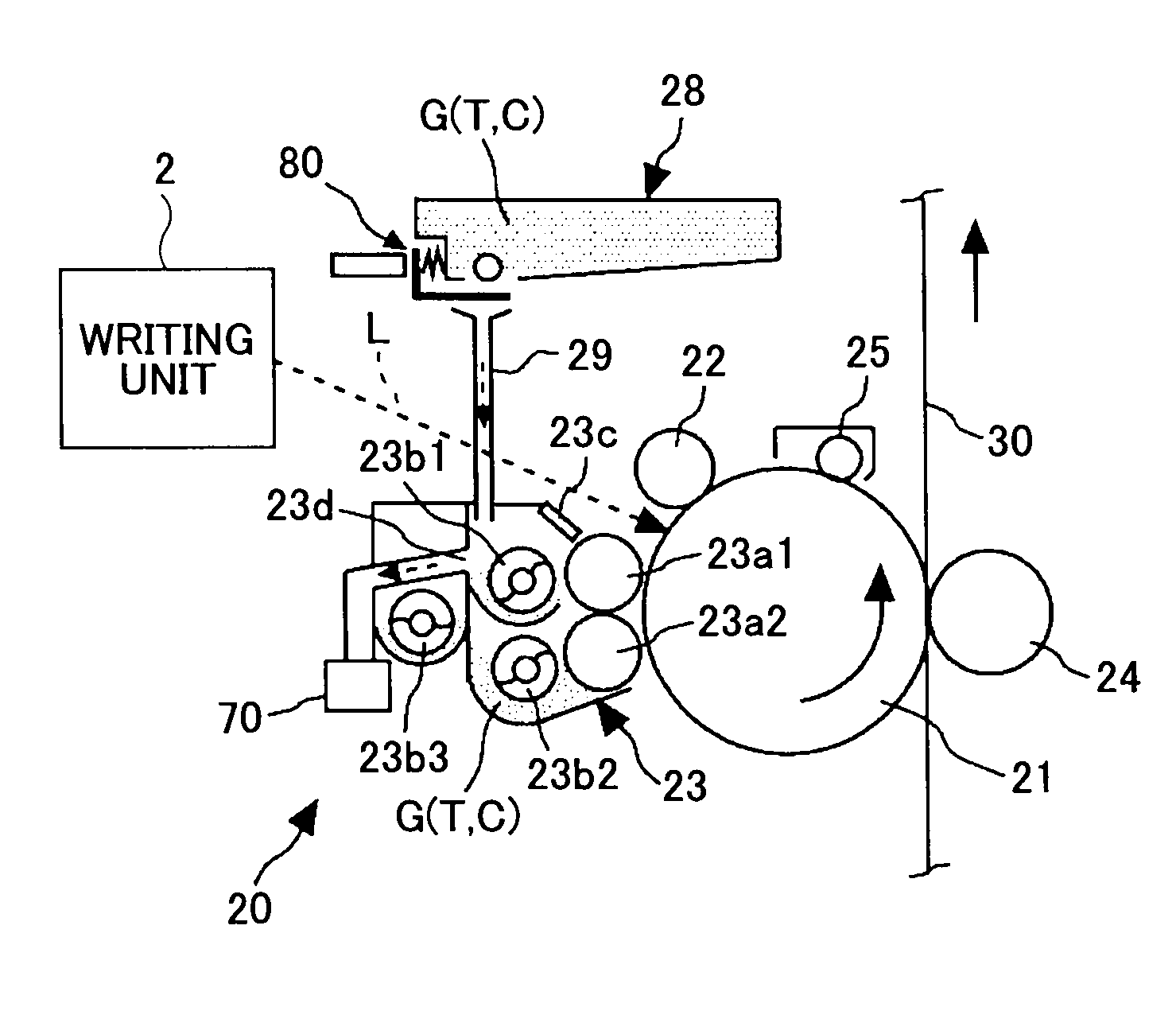
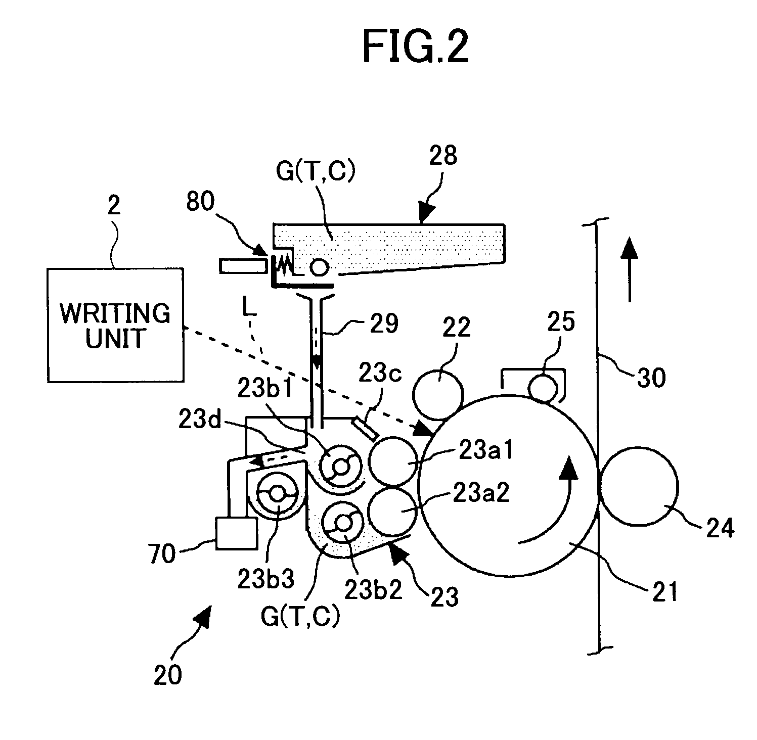
[0031]Writing units 2A through 2D are for writing electrostatic latent images on corresponding photoconductive drums 21 (image carriers) after a charging procedure is performed based on image information. The writing units 2A through 2D are optical scanning devices including polygon mirrors 3A through 3D and optical elements 4A through 4D, respectively. It is possible to use LED arrays instead of optical scanning devices as the writing units.

[0032]A sheet feeding unit 61 stores transfer materials P onto which images are to be transferred, such as recording paper and OHP transparencies. At the time of forming an image, the sheet feeding unit 61 feeds the transfer materials P to a transfer belt 30 by rotating a sheet feeding rolle...

second embodiment

[0100]A second embodiment according to the present invention is described in detail with reference to FIG. 8.

[0101]FIG. 8 is a cross-sectional view of the third developer conveying unit of a developing device according to the second embodiment, viewed from the X direction of FIG. 3. The developing device according to the second embodiment is different from that of the first embodiment in that the third developer conveying unit B3 is provided with an internal pressure adjusting unit N, a ventilation hole 23r, and a filter 75.

[0102]Similar to that of the first embodiment, the developing device 23 according to the second embodiment is provided with the three developer conveying units B1 through B3 that form the circulating paths for conveying the developer G accommodated in the developing device 23.

[0103]In the second embodiment, as shown in FIG. 8, the internal pressure adjusting unit N is provided in the third developer conveying unit B3 in such a manner that a height h1 from the sur...

third embodiment

[0108]A third embodiment according to the present invention is described in detail with reference to FIG. 9.

[0109]FIG. 9 is a cross-sectional view of a developing device according to the third embodiment. The developing device according to the third embodiment is different from that of the first embodiment in that a ventilation path 23s is provided for directly connecting the first developer conveying unit B1 to the second developer conveying unit B2.

[0110]Similar to that of the first embodiment, the developing device 23 according to the third embodiment is provided with the three developer conveying units B1 through B3 that form the circulating paths for conveying the developer G accommodated in the developing device 23.

[0111]In the third embodiment, as shown in FIG. 9, the ventilation path 23s is provided so that the first developer conveying unit B1 is in direct communication with the second developer conveying unit B2. The ventilation path 23s is positioned such that its opening...


PUM


Abstract

A disclosed developing device is for accommodating a developer including carriers and a toner, and for developing a latent image formed on an image carrier. The developing device includes plural developer conveying units configured to convey the developer accommodated in the developing device and form circulating paths; and a ventilation unit configured to perform ventilation between at least one of the developer conveying units whose internal pressure increases and at least one of the developer conveying units whose internal pressure decreases.

Description

BACKGROUND OF THE INVENTION[0001]1. Field of the Invention[0002]The present invention relates generally to image forming apparatuses employing an electrophotographic method, such as copiers, printers, facsimile machines, or a multifunction peripheral including these functions, and also to developing devices and process cartridges that are provided in such image forming apparatuses. More particularly, the present invention relates to a developing device, a process cartridge, and an image forming apparatus including plural developer conveying units forming circulating paths for the developer.[0003]2. Description of the Related Art[0004]Conventionally, there is known an image forming apparatus such as a copier or a printer provided with a developing device accommodating a two-component developer (in which an additive may be added) including a toner and carriers. Plural developer conveying units are provided in the developing device for performing a developing procedure by circulating t...

Claims


Application Information

Patent Timeline
IPC IPC(8): G03G21/20
CPCG03G15/0898G03G2215/0838G03G2215/0822
Inventor KUBO, TATSUYAFUJINUMA, YOSHITAKATATEYAMA, SUSUMUNAKAYAMA, MASAYOSHI
Owner RICOH KK
Features
  • Generate Ideas
  • Intellectual Property
  • Life Sciences
  • Materials
  • Tech Scout
  • Unparalleled Data Quality
  • Higher Quality Content
  • 60% Fewer Hallucinations
Learn More