
Toner cartridge

a technology of toner cartridges and cartridge covers, applied in the field of toner cartridges, can solve the problems of deteriorating image quality, affecting the operation of genuine toner, and the possibility of attaching the case cover again to the toner bottle case, so as to achieve the effect of efficient refilling of genuine toner

Inactive Publication Date: 2008-08-21
MURATA MASCH LTD
View PDF10 Cites 5 Cited by
  • Summary
  • Abstract
  • Description
  • Claims
  • Application Information

AI Technical Summary

Benefits of technology

[0011]In order to overcome the problems described above, preferred embodiments of the present invention prevent the non-genuine toner from being refilled in the toner cartridge for the image forming apparatus and to efficiently carry out a refill operation of the genuine toner by a manufacturer, etc.
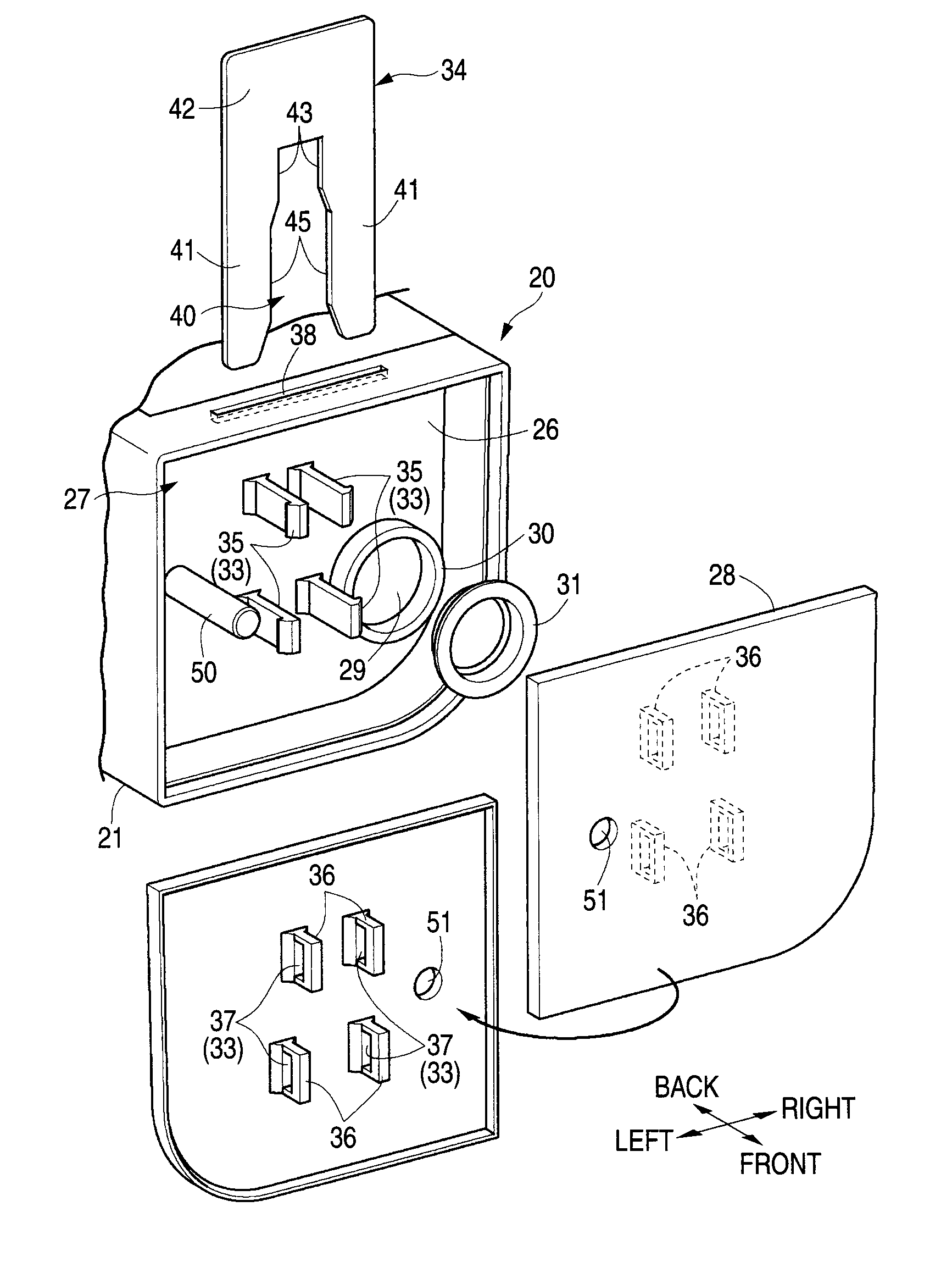
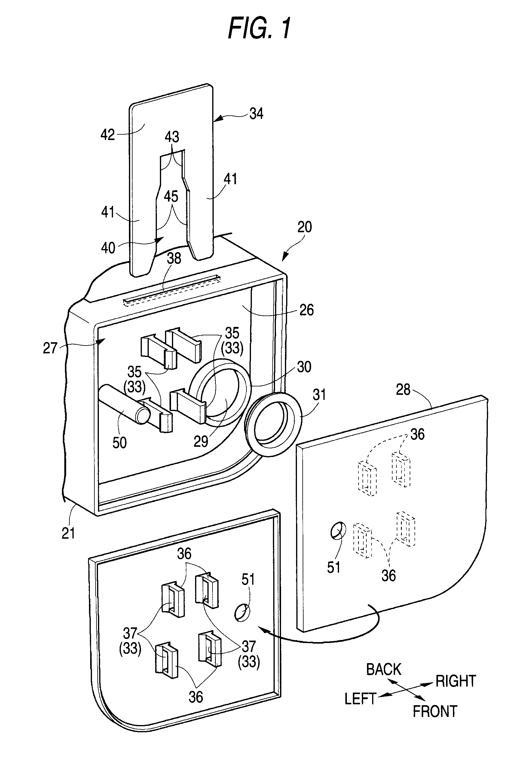
[0012]According to a preferred embodiment of the present invention, a toner cartridge includes a toner chamber which is provided in a case main body to contain a toner; a filling hole which is provided in an outer surface of the case main body to fill the toner into the toner chamber; and a cover member which is attached to the outer surface of the case main body to cover the filling hole. The cover member is detachably attached to the case main body by a lock mechanism located between the case main body and the cover member. The lock mechanism has two or more lock structures which lock the cover member to the case main body and a release tool which carries out a lock release operation of the lock structures. Each of the lock structures has an elastic engagement claw and an engagement recess which are provided on opposite surfaces of the case main body and the cover member, respectively. The release tool allows all of the elastic engagement claws to be simultaneously displaced in a lock release direction.

Problems solved by technology

However, when the toner different from a genuine toner is refilled by the recycling manufacturer, image quality formed by an image forming apparatus may easily deteriorate.
When a non-genuine toner is refilled, a performance of the image forming apparatus is not sufficiently exhibited, which eventually deteriorates image quality.
That is, when a new lock member is not provided, it is not possible to attach again the case cover to the toner bottle case.
Accordingly, in order to recycle the toner cartridge, it is necessary to prepare a spare lock member, and thus it is difficult to manufacture a toner cartridge of a recyclable product in which the non-genuine toner is refilled.
In the method disclosed in JP-A-2002-258595, a problem arises in that an attachment / detachment operation of the lock member is difficult and even when the genuine toner is refilled by a manufacturer or a regular distributor, etc.
(hereinafter, referred to as a manufacturer, etc.), the attachment / detachment operation of the lock member is troublesome.
As a result, work efficiency may easily deteriorate.
Accordingly, it is difficult and troublesome to carry out a series of operations.
Additionally, since the spare lock member needs to be prepared, it is disadvantageous in that a cost of the toner cartridge of the recycle product necessarily increases.

Method used


Image

  • Toner cartridge
  • Toner cartridge
  • Toner cartridge

Examples


first preferred embodiment

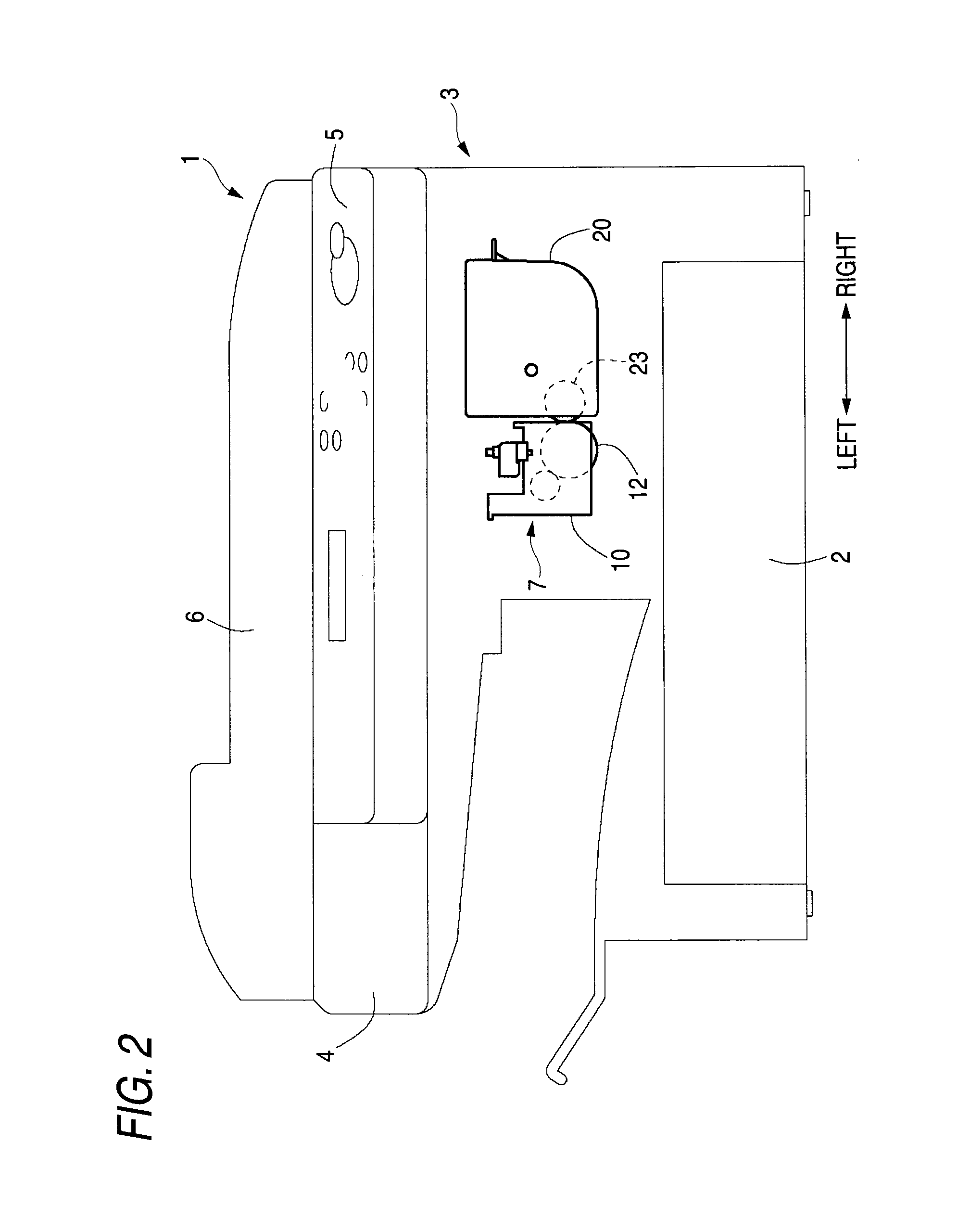
[0033]FIGS. 1 to 6 show a first preferred embodiment in which a toner cartridge according to the present invention is used as that of a multi-function machine preferably including a copy function and a facsimile function. In FIG. 2, the multi-function machine (image forming apparatus) 1 includes a sheet feeding cassette 2, an image printing unit 3 which performs an image printing operation on a print sheet fed from the sheet feeding cassette 2 through a sheet feeding passage, and an image readout unit 4 which is disposed above the image printing part 3. On the upper surface of the image readout unit 4, an operation panel 5 with various operation buttons and an automatic document feeder (ADF) 6 are provided.

[0034]In the present preferred embodiment, for the convenience of description, an extension direction of the operation panel 5 is referred to as a left / right direction (see FIG. 2). Additionally, a direction which is horizontally perpendicular to the left / right direction is referr...

second preferred embodiment

[0050]The toner cartridge according to a second preferred embodiment of the invention will be described with reference to FIGS. 7 and 8. As the lock mechanism according to the present preferred embodiment, three lock structures 33 are preferably disposed at different positions from the release operation hole 38. The downward direction of each of the elastic engagement claws 35 serving as each of the lock structures 33 is set to a lock release direction. Accordingly, the release tool 34 does not include a portion corresponding to the operation groove 40 according to the first preferred embodiment, but includes a horizontal operation surface 48 which extends in the left / right direction so as to correspond to each of the lock structures 33. Since the other configurations are preferably the same as those of the first preferred embodiment, the same reference numerals are given to the same components and the description thereof will be omitted. Additionally, in the second preferred embodi...


PUM


Abstract

In a toner cartridge, a cover member is attached to an outer surface of a case main body so as to cover a filling hole through which a toner is filled in a toner chamber. The cover member is detachably attached to the case main body by a lock mechanism disposed between the case main body and the cover member. The lock mechanism includes two or more lock structures which lock the cover member to the case main body and a release tool which carries out a release operation of the lock structures. Each of the lock structures includes an elastic engagement claw and an engagement recess which are provided on opposite surfaces of the case main body and the cover member, respectively. The release tool is configured to allow all of the elastic engagement claws to be simultaneously displaced in a lock release direction.

Description

BACKGROUND OF THE INVENTION[0001]1. Field of the Invention[0002]The present invention relates to a toner cartridge that is detachably attached to the inside of an electro-photographic type image forming apparatus to supply a toner to a developer unit.[0003]2. Description of Related Art[0004]In the past, in such an electro-photographic type image forming apparatus, a toner replenishment system called a cartridge replacement type in which a toner can be replenished by replacing a toner cartridge has been widely used. In a case of the toner cartridge of the cartridge replacement type, a filling hole through which the toner is filled into a toner chamber is provided, and the filling hole is sealed in an air-tight manner by pressing a cap toward the filling hole after filling the toner therein at the time of shipment from a factory. The toner can be refilled into the toner chamber. In this case, the toner is input therein through the filling hole after the cap is separated therefrom. Sub...

Claims


Application Information

Patent Timeline
Patent Type & Authority Applications(United States)
IPC IPC(8): G03G15/08
CPCG03G15/0894G03G2215/00987G03G15/0855G03G15/0865G03G15/0875G03G15/08
Inventor KAWAI, HIDEAKI
Owner MURATA MASCH LTD
Learn More