Method and system for uncorrectable error detection

a technology of error detection and error correction, applied in the field of error correction codes, can solve problems such as unresolved problems, multi-bit errors, and inability to correct, and achieve the effects of improving the accuracy of error detection, and increasing the difficulty of ue detection

Inactive Publication Date: 2008-08-21
IBM CORP
View PDF6 Cites 74 Cited by
  • Summary
  • Abstract
  • Description
  • Claims
  • Application Information

AI Technical Summary

Benefits of technology

[0010]A system, method and program product for utilizing error correction code (ECC) logic to detect multi-bit errors are disclosed herein. In one embodiment, a first test pattern and a second test pattern are applied to a set of hardware bit positions. The first and second patterns are multiple logic level patterns and the second test pattern is the logical complement of the first test pattern. The first and second test patterns are utilized by the ECC logic to detect correctable errors having n or fewer bits. One or more bit positions of a first correctable error occurring responsive to applying the first test pattern are determined and one or more bit positions of a second correctable error occurring responsive to applying the second test pattern are determined. The determined bit positions of the first and second correctable errors are processed to identify a multiple-bit error within the set of hardware bit positions.

Problems solved by technology

Such ECCs are often further enabled to detect, but not correct, multi-bit errors known as uncorrectable errors (UEs).
UE detection becomes even more difficult when the faulty bit locations are not persistently stuck at particular levels, but instead fail intermittently.
While improving the reliability of detecting UEs having bad bits stuck at multiple logic levels, several problems remain unresolved.
Conventional multi-pattern ECC testing also fails to adequately address the problem of intermittently occurring multiple-bit errors.
For both the bit spread issue and intermittent fault issue, increasing the number of patterns expands UE detection coverage, but also increases the costs associated with extra test pattern coverage.

Method used


Image

  • Method and system for uncorrectable error detection
  • Method and system for uncorrectable error detection
  • Method and system for uncorrectable error detection

Examples


Embodiment Construction

)

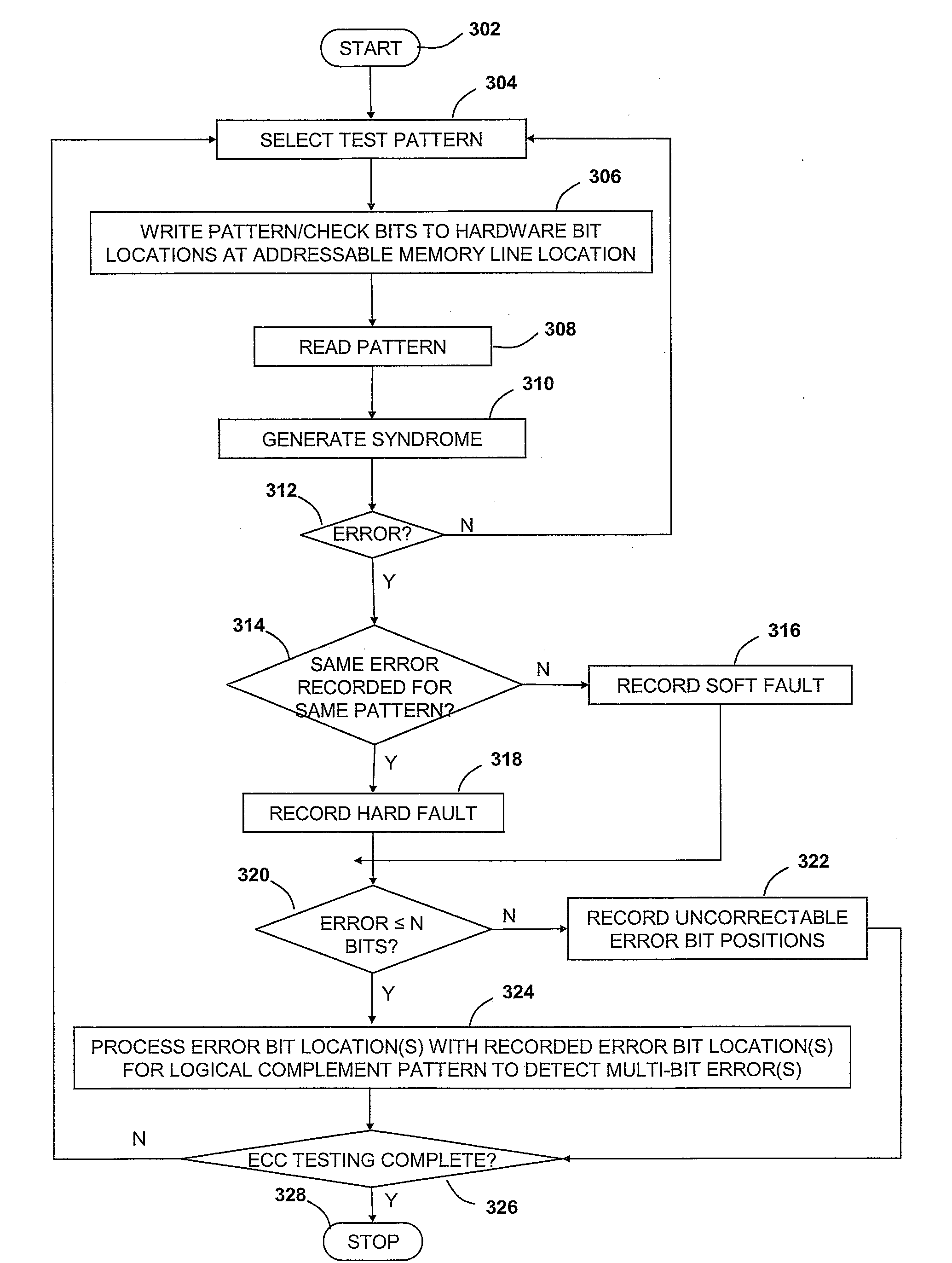
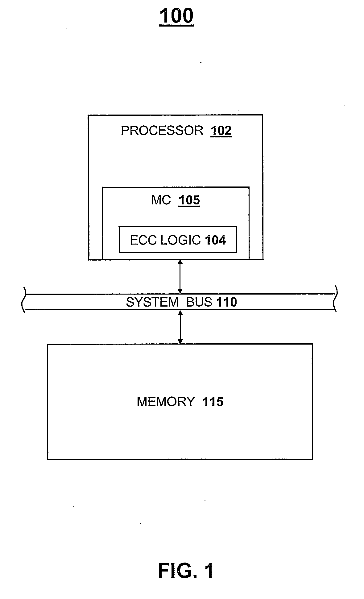
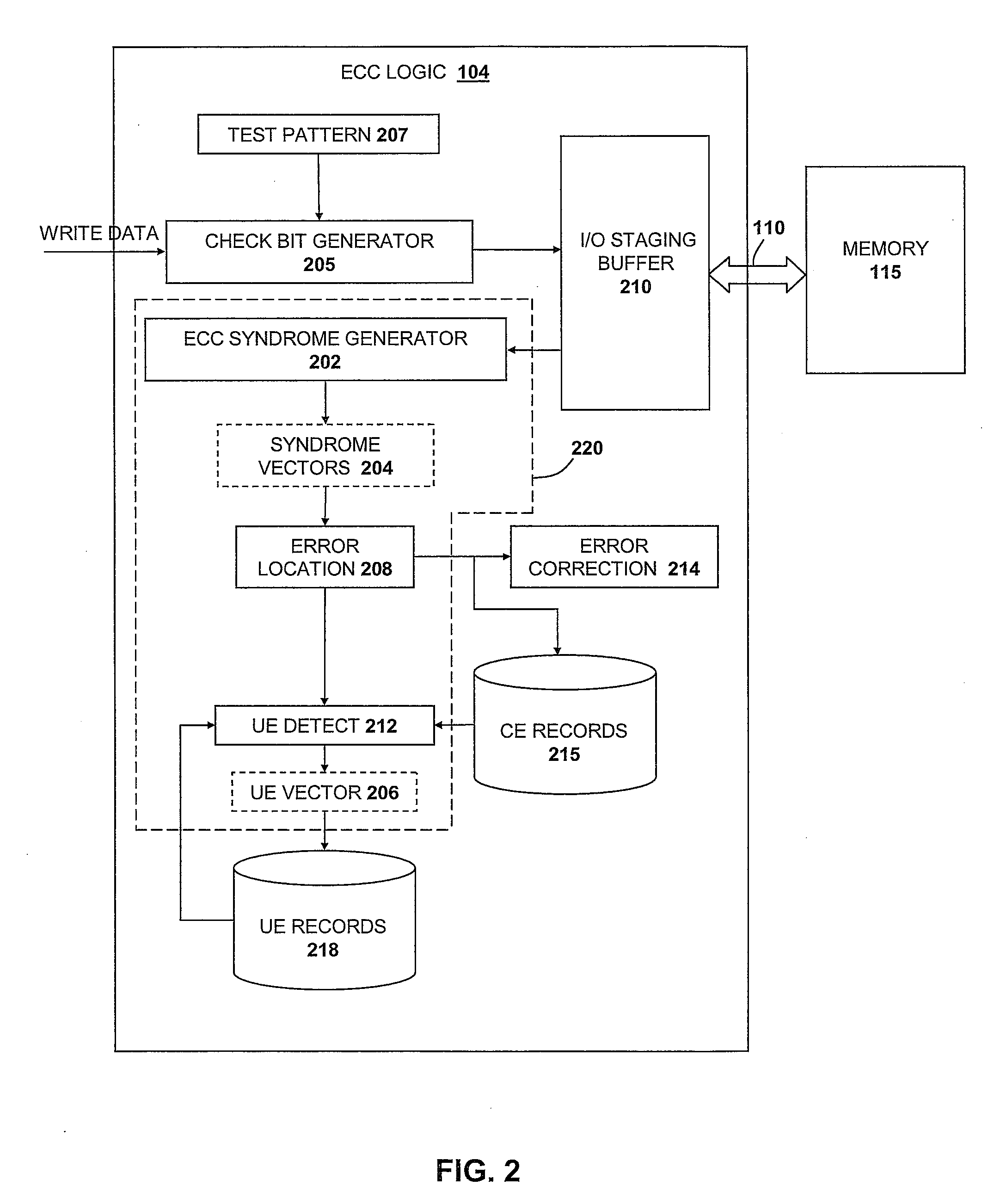
[0019]The present invention is directed to a method and system for utilizing correctable error (CE) analysis to identify otherwise undetected multi-bit errors. Specifically, and as depicted and described below with reference to the figures, the present invention utilizes CE and uncorrectable error (UE) logging mechanisms in combination with error detection mechanisms native to conventional error correction code (ECC) logic to detect multi-bit errors falling outside the scope of errors defined by the ECC logic as being correctable. In the depicted embodiments, the multi-bit error detection method and system are implemented within a memory system in which ECC logic is utilized to detect and correct errors within memory devices. It should be noted that the invention may be more widely applicable to other devices in which data is stored in and / or transported to and from designated hardware bit storage or transport devices such as in registers, buffers, bitlines, etc. that may be includ...


PUM


Abstract

A system, method and program product for utilizing error correction code (ECC) logic to detect multi-bit errors. In one embodiment, a first test pattern and a second test pattern are applied to a set of hardware bit positions. The first and second patterns are multiple logic level patterns and the second test pattern is the logical complement of the first test pattern. The first and second test patterns are utilized by the ECC logic to detect correctable errors having n or fewer bits. One or more bit positions of a first correctable error occurring responsive to applying the first test pattern are determined and one or more bit positions of a second correctable error occurring responsive to applying the second test pattern are determined. The determined bit positions of the first and second correctable errors are processed to identify a multiple-bit error within the set of hardware bit positions.

Description

BACKGROUND OF THE INVENTION[0001]1. Technical Field[0002]The present invention relates generally to error correction codes, and in particular, to utilizing correctable error analysis to identify otherwise undetected multi-bit errors.[0003]2. Description of the Related Art[0004]Many hardware diagnostic tests for memory arrays or buses rely on hardware-generated error correction codes (ECCs) which detect and correct single-bit errors known as correctable errors (CEs). Such ECCs are often further enabled to detect, but not correct, multi-bit errors known as uncorrectable errors (UEs). A primary goal of ECC diagnostics testing is to identify the locations of UEs so that hardware containing UEs can be deconfigured.[0005]Robust ECC testing procedures have long been recognized as a practical necessity for main storage on large scale computer systems such as the S / 390 Parallel Enterprise Server systems available from IBM Corporation. S / 390 and IBM are registered trademarks, and S / 390 Parall...

Claims


Application Information

Patent Timeline
Patent Type & Authority Applications(United States)
IPC IPC(8): G11C29/52
CPCG06F11/1044G11C29/42G11C2029/1208G11C29/4401G11C29/44
Inventor GOLLUB, MARC A
Owner IBM CORP
Why Eureka
Try Eureka