System For Monitoring a Container

a container and monitoring system technology, applied in sustainable waste treatment, manufacturing tools, instruments, etc., can solve the problems of time and energy consumption of haulers, complicated coordination, and complicated tasks, so as to optimize the return on investment, reduce long-term costs, and eliminate costly instances

Inactive Publication Date: 2008-08-28
ADVANCED CUSTOM ENGINEERED SYST & EQUIP
View PDF89 Cites 64 Cited by
  • Summary
  • Abstract
  • Description
  • Claims
  • Application Information

AI Technical Summary

Benefits of technology

[0018]The antenna is mounted on a wall and an opening is provided in the wall between the antenna and the items in the container to enhance signal communications between the antenna and items in the container. The antenna is further shielded from external noise (e.g., other identification tags located outside the container) by encasing it in a metal, except for the opening. A data line may be disposed between the antenna and a reader. In the alternative, the antenna and reader can be wirelessly connected. The reader is in turn connected to means for recording the identification information and / or means for communicating the identification information associated with the tags. The reader is connected to the PLC and / or to a remote location such as a central station. The antenna is thusly connected to a control panel via the reader; the read information is stored and / or transmitting to another system such as a central station.
[0020]Additionally, the container can have a door. The antenna can be mounted thereon with an opening in the door being provided between the antenna and the items in the container to enhance signal communications between the antenna and items in the container. The door, movable between an open position and a closed position, also has a sensor in communications with a switch to detect the door in either the open position or the closed position and to turn the antenna on only when the door is in the closed position and turn the antenna off when the door is in the open position.
[0021]A method incorporating the above system is also disclosed. The method of reading identification information on tags with each tag being attached to an item in a waste container, comprises the steps of securing an antenna to a wall of the container for reading the identification information on the tags within the container, transmitting the information to a reader, and recording the identification information and / or communicating the identification information associated with the tags to a separate location. The step of securing the antenna further includes providing an opening in the wall between the antenna and the items in the container to enhance signal communications between the antenna and items in the container. The method further includes the step of shielding the antenna from external noise by encasing it in a metal, except for the opening. The wall may also include a door with the antenna being secured to the door.
[0026]It is believed this system can nearly eliminate instances of costly misdirected or unnecessary service dispatch and call center activity, as well as MMS (Maintenance Management System) frustration. The present system is capable of managing assets (e.g., equipment) to their peak performance, optimizing the return on investment. This objective is achieved combining asset and service management with clear definitions. As a result, service level agreements can be had at lower long-term costs, with automated response plans for proactive equipment and supply chain management.
[0027]In summary, this single on-line platform enables successful equipment service and management of hauling services with the added value of collecting accurate inventory and product specific data to provide complete user ready RFID systems benefiting inventory management and loss prevention.

Problems solved by technology

For large organizations this can be a very complicated task as there are many haulers and many customers needing their trash and recyclables collected, picked-up and hauled away.
This, too, requires time and energy for the haulers and / or representatives (of the service provider) to monitor and inspect.
For large organizations this can be a very complicated to coordinate.
It can also be complicated to verify the charges for these services are fair and accurate, as there are many service providers and many customers needing their compactors, bins and balers repaired.
However, it is believed no one successfully monitors such tags as they leave a facility.

Method used


Image

  • System For Monitoring a Container
  • System For Monitoring a Container
  • System For Monitoring a Container

Examples


Embodiment Construction

[0038]While this invention is susceptible of embodiments in many different forms, there is shown in the drawings and will herein be described in detail, preferred embodiments of the invention with the understanding the present disclosure is to be considered as an exemplification of the principles of the invention and is not intended to limit the broad aspect of the invention to the embodiments illustrated. The present invention will have the following main components and techniques for operation of the device.

[0039]For the purposes of the present disclosure, the term “waste” is used in its broadest sense and includes trash and recyclables. It not only includes items being destroyed or put in a landfill, such as trash, but also recyclables, such as paper, corrugation board, cardboard, etc.

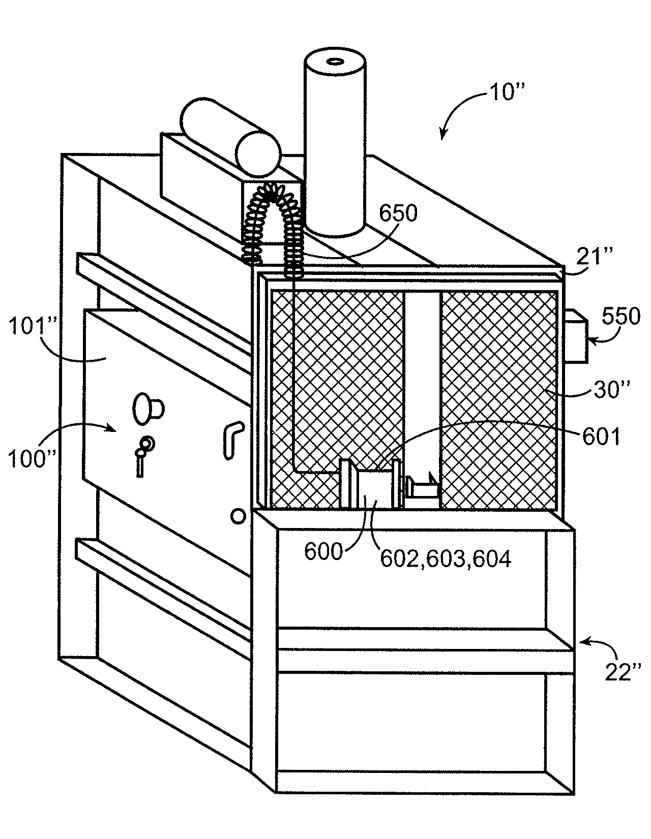
[0040]The term “container” is also used in its broadest sense and can include bins, balers, compactors, etc. for holding waste and / or recyclables.

General Configuration of the System 10
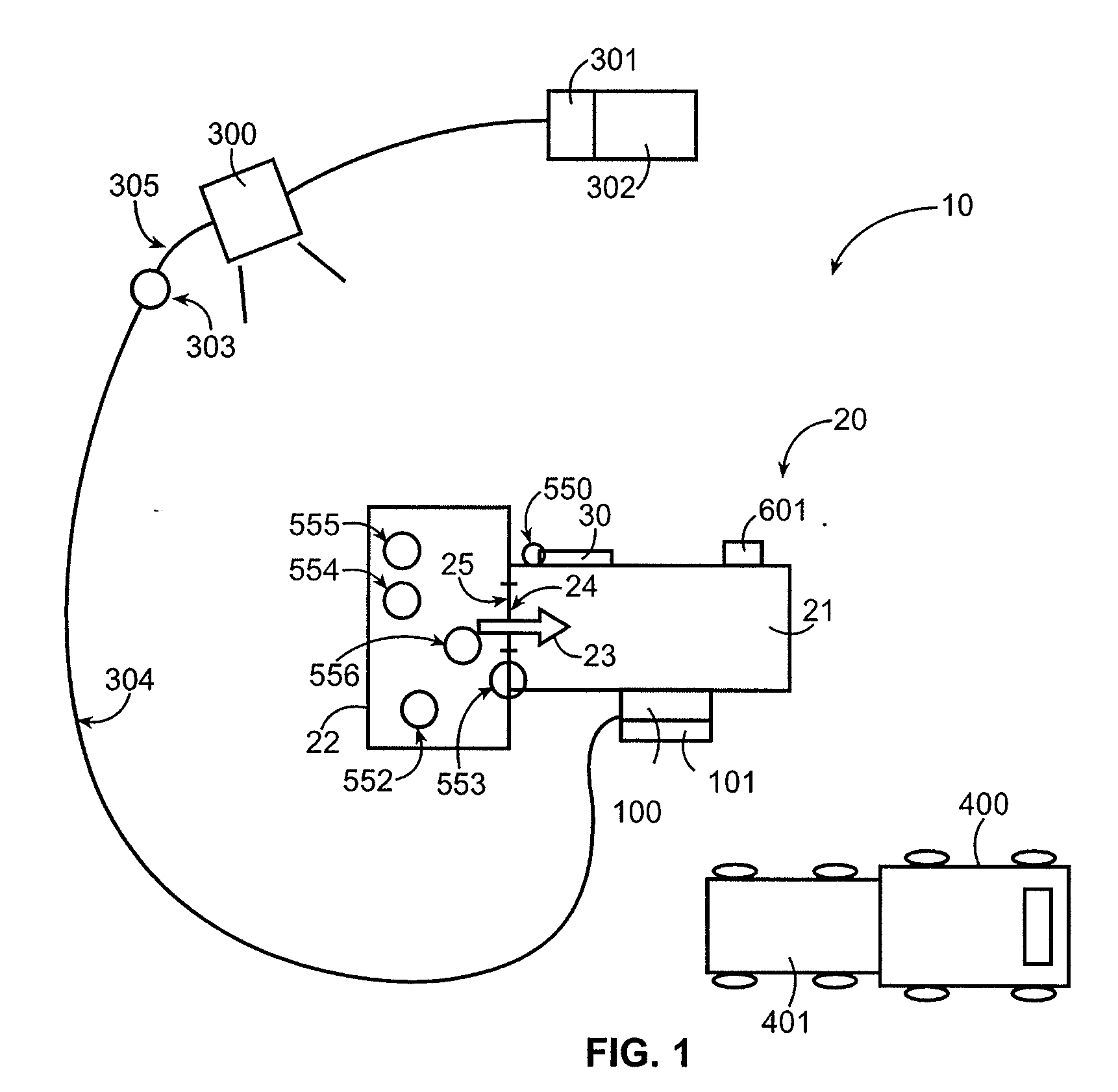
[0041]FIG. 1 s...


PUM


Abstract

A container having a compactor and bin for waste is disclosed permitting on-premises and remote monitoring of the system and collection is disclosed. The system can also detect non-complaint materials placed therein and act thereon. Methods are further disclosed for inventorying identification tags for tracking packages, merchandise and tags disposed of.

Description

CROSS-REFERENCE TO RELATED APPLICATIONS[0001]This application is a Nonprovisional application claiming priority to U.S. Provisional Patent Application No. 60 / 902,462, filed Feb. 21, 2007, which is herein incorporated by reference.TECHNICAL FIELD[0002]The present invention relates to the management of trash and recyclables and the equipment associated with it, and in particular, the remote monitoring and controlling of waste equipment (e.g., containers, bins, balers and compactors) and the trash and recyclables therein and recycling thereof. The equipment can be located at several locations and monitored from several locations, such as a central station, by several different techniques, such as over the internet, over an ethernet, by cell phone lines / towers and via regular phone lines. The invention also includes a system incorporating methods and apparatuses relating to product information, such as RFID tags or others, passing though the equipment. The product information can be use...

Claims


Application Information

Patent Timeline
Patent Type & Authority Applications(United States)
IPC IPC(8): B30B15/16B30B15/26
CPCB30B9/3007G06Q10/087B30B9/3042Y02P90/84G06F16/9554Y02W90/00G06K7/10297G06K7/10316G06K7/10415
Inventor FLOOD, CHRISTOPHER M.
Owner ADVANCED CUSTOM ENGINEERED SYST & EQUIP
Why Eureka
Try Eureka