
Powered Rope Ascender and Portable Rope Pulling Device

a technology of power rope and ascender, which is applied in the direction of hoisting equipment, sport apparatus, building scaffolding, etc., can solve the problems of fatigue and injury, inability to manually lift or pull heavy objects, and limited usefulness of winches

Active Publication Date: 2008-08-28
ATLAS DEVICES
View PDF63 Cites 18 Cited by
  • Summary
  • Abstract
  • Description
  • Claims
  • Application Information

AI Technical Summary

Benefits of technology

[0029]A device of the invention can conveniently be configured as a portable hand-held device, and in particular, can be configured as a portable

Problems solved by technology

Manually lifting or pulling heavy objects is not a viable option due to the strength required to lift or pull such objects.
Often, fatigue and injury result from manually lifting or pulling such objects.
However, winches are limited in their usefulness for several reasons.
First, the cable or rope is fixed permanently to the drum, which limits the maximum pull distance and restricts the towing medium to only that rope or cable.
Second, the winch must be fixed to a solid structure to be used, limiting its placement and usability.
Third, controlled release of tension is not a capability of many winches, further limiting usability.
Passive ascenders such as these are severely limited in their usefulness for several reasons.
First, they rely on the strength of the user for upward mobility.
Thus, passive ascenders are not useful in rescue situations where an injured person needs to move up a rope.
Second, the need to grip one ascender with each hand limits multi-tasking during an ascent because both hands are in use.
Third, the rate and extent of an ascent are limited to the capabilities of the user.
Fourth, the diamond grit used to grip the rope is often too abrasive, destroying climbing ropes for future use.
Fifth, the type of rope to be used is limited by what the ascenders' one-way locks can interact properly with.
Passive rope ascenders are useless for moving a dead weight load upward along a rope.
Thus, this powered device is limited in its usefulness by the same factors mentioned above.
In addition, the lifting capacity and rate of ascent are is limited by the power source that fuels the pneumatic piston.
A further drawback of this design is that at any reasonable rate the load will experience a significant jerking motion in the upward direction during an ascent.
Therefore, fragile loads will be at risk if this device is used.

Method used


Image

  • Powered Rope Ascender and Portable Rope Pulling Device
  • Powered Rope Ascender and Portable Rope Pulling Device
  • Powered Rope Ascender and Portable Rope Pulling Device

Examples


Embodiment Construction

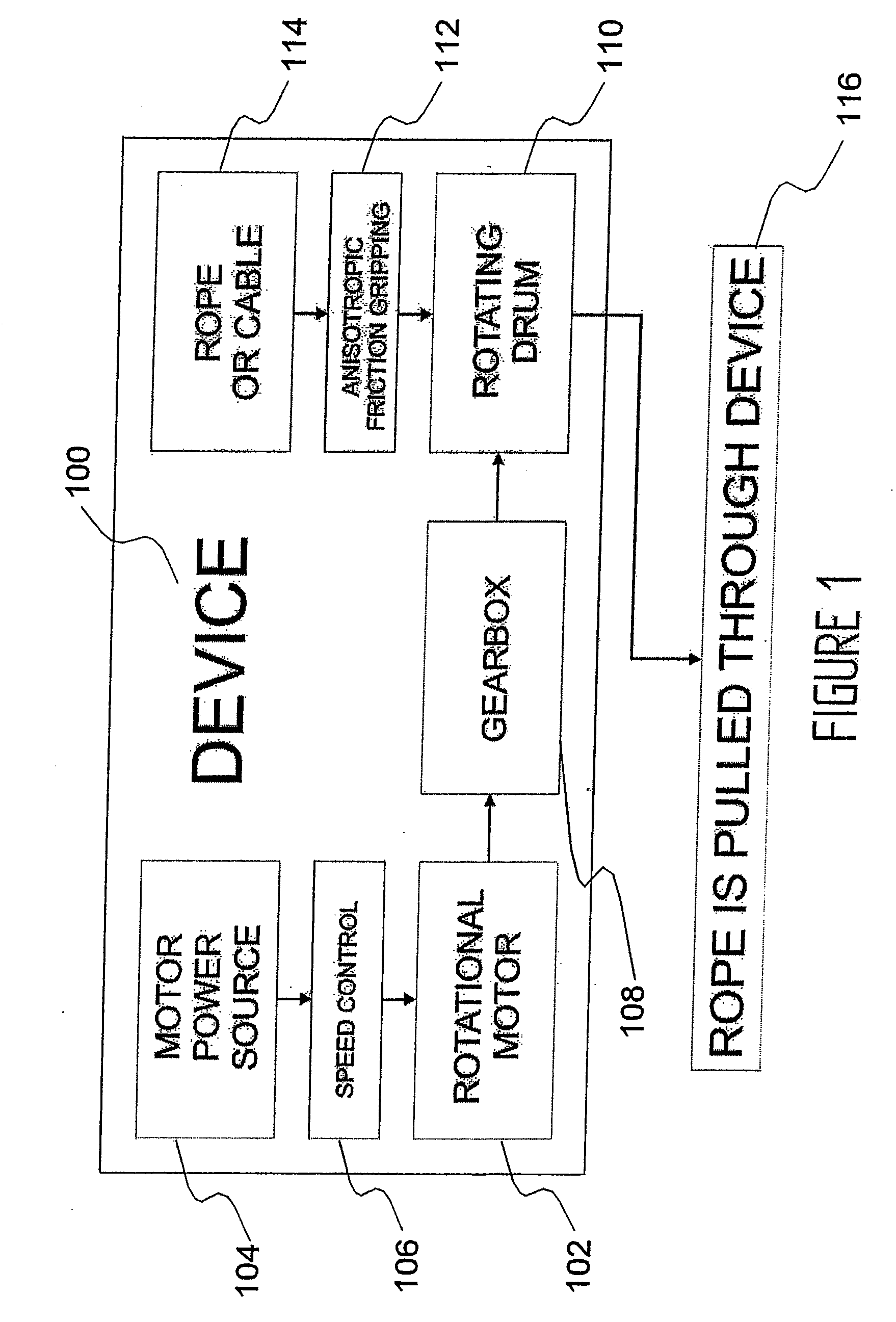
[0048]Referring now to FIG. 1, a device 100 of the invention for pulling a resilient elongate element such as a cable or a rope 114 is illustrated diagrammatically. The device includes a rotational motor 102 from which the pulling motion of the device is derived. A number of different types of motors, such as two or four stroke internal combustion engines, or ac or dc powered electric motors, could be employed to provide the rotational motion desired for pulling the rope or cable. A motor power source 104 can also be included that is appropriate to the rotational motor used, such as gasoline or other petroleum products, a fuel cell, or electrical energy supplied in ac (such as from a power outlet in a typical building) or dc (such as from a battery) form. In one preferred embodiment, the rotational motor is a dc electric motor and the motor power source is one or more rechargeable lithium ion batteries.

[0049]The rotational motor can also have speed control 106 and / or a gearbox 108 a...


PUM


Abstract

A device for pulling an elongate member includes a rotational motor having an output and a rotating drum connected to the output of said rotational motor. The device further includes a guide mechanism for guiding the resilient elongate element onto, around at least a portion of the circumference of, and off of, the rotating drum. When the rotational motor turns the rotating drum, the rotating drum thereby continuously pulls the resilient elongate element through the device.

Description

RELATED APPLICATIONS[0001]This application is a continuation-in-part of U.S. patent application Ser. No. 11 / 780,596 to Ball et al., entitled “Powered Rope Ascender and Portable Rope Pulling Device,” filed on Jul. 20, 2007; which application is a continuation of U.S. patent application Ser. No. 11 / 376,721 to Ball et al., entitled “Powered Rope Ascender and Portable Rope Pulling Device,” filed on Mar. 15, 2006; which application claims priority to U.S. Provisional Application No. 60 / 673,212, filed Apr. 20, 2005, entitled “Powered Rope Ascender and Portable Rope Pulling Device,” and U.S. Provisional Application No. 60 / 717,343, filed Sep. 15, 2005, entitled “Powered Rope Ascender and Portable Rope Pulling Device,” all of which are incorporated by reference herein. This application also claim priority to U.S. Provisional Application No. 60 / 891,779 to Ball et al., filed Feb. 27, 2007, entitled “Modified Self-Tailing Mechanism for Use as a Rope Winch or Powered Ascent Device,” which applic...

Claims


Application Information

Patent Timeline
IPC IPC(8): B66D1/14
CPCA62B1/10B66D1/7415B66D1/7494B66D1/7489B66D1/7447
Inventor BALL, NATHANFOFONOFF, TIMOTHYSCHMID, BRYANWALKER, DANIEL
Owner ATLAS DEVICES
Features
  • Generate Ideas
  • Intellectual Property
  • Life Sciences
  • Materials
  • Tech Scout
  • Unparalleled Data Quality
  • Higher Quality Content
  • 60% Fewer Hallucinations
Learn More