
4-bar hinge system for cab-high load bed cover adaptation to rear lift access

a technology of rear lift access and hinge system, which is applied in the direction of roofs, load transportation vehicles, vehicle components, etc., can solve the problems of structural flex and associated stresses, and the extent and effect of such stresses are not adequately addressed

Inactive Publication Date: 2008-08-28
TRAIL R VAN
View PDF13 Cites 13 Cited by
  • Summary
  • Abstract
  • Description
  • Claims
  • Application Information

AI Technical Summary

Benefits of technology

The patent aims to offer a solution that allows pickup trucks to easily adapt to different load management accessory rail systems. This results in improved efficiency and flexibility for pickup trucks in managing various loads.

Problems solved by technology

The technical problem addressed in this patent is to provide a simple and cost-effective solution for attaching a cab high load bed cover to a vehicle load bed, allowing rear lift while keeping the cap upper forward edge clear of the vehicle cab, while also being adaptable to a variety of production caps and maintaining functional robustness. The existing solutions in the market have limitations in terms of cost and complexity, and do not provide optimal loading access.

Method used


Image

  • 4-bar hinge system for cab-high load bed cover adaptation to rear lift access
  • 4-bar hinge system for cab-high load bed cover adaptation to rear lift access
  • 4-bar hinge system for cab-high load bed cover adaptation to rear lift access

Examples


Embodiment Construction

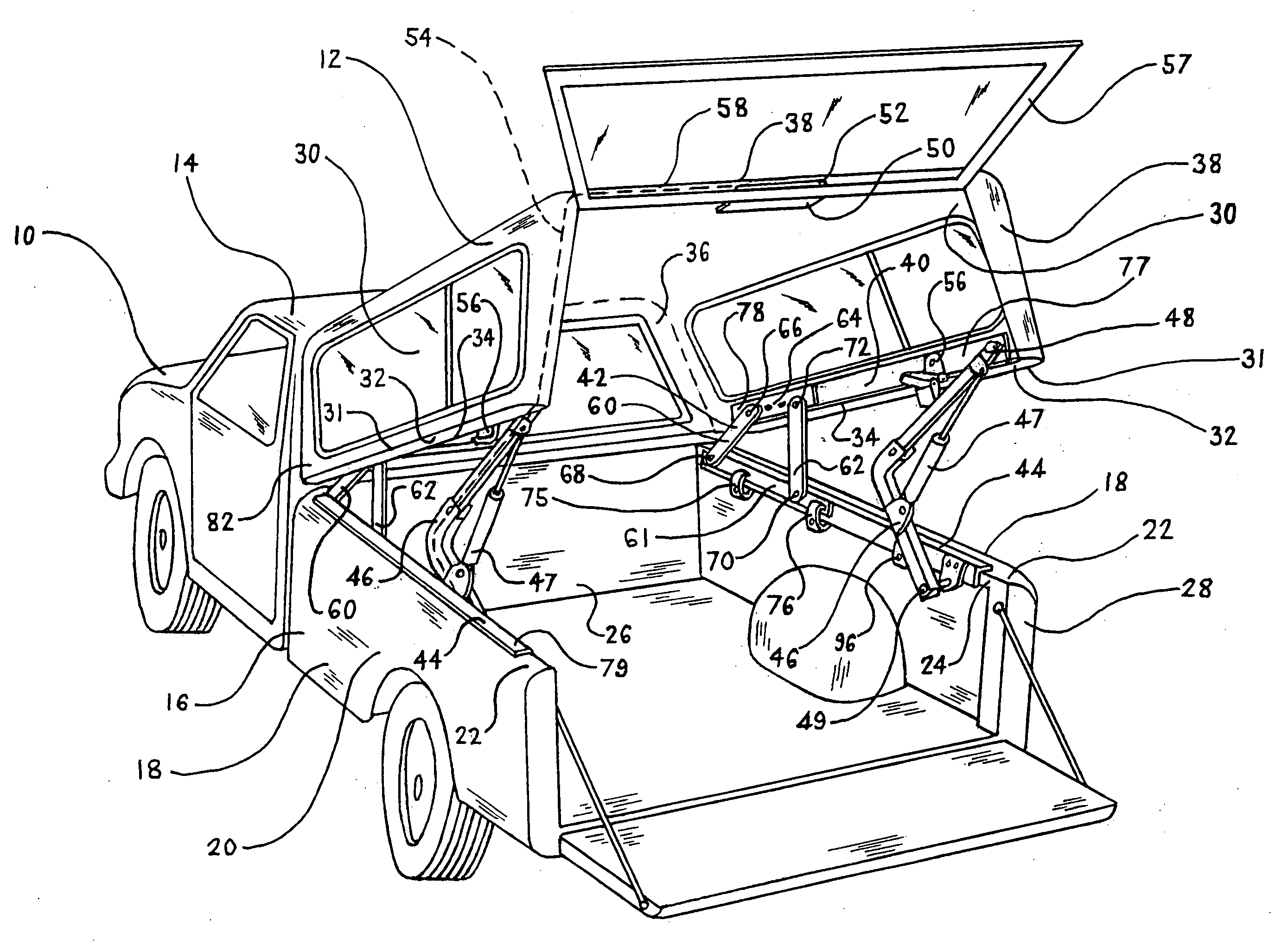
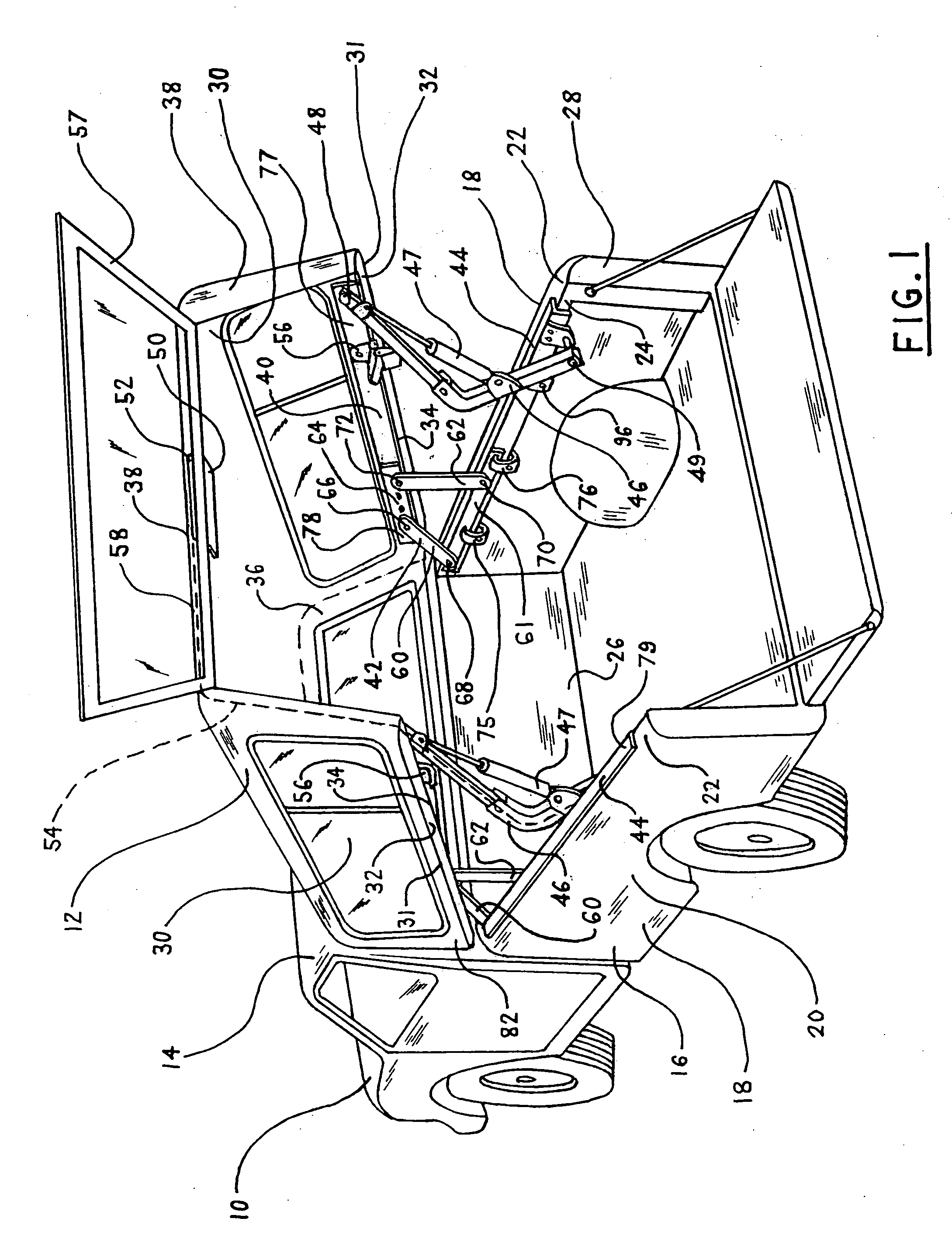
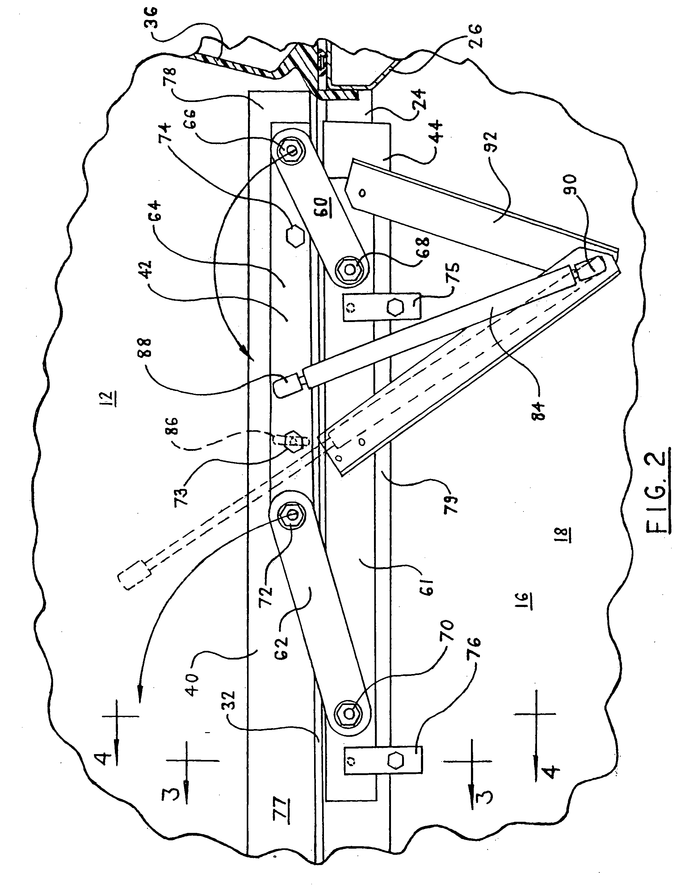
[0043]Referring to FIG. 1: As installed on a pickup truck 10, a cab high load bed cover (cap) 12 is mounted behind a passenger cab 14 on a load bed 16 including side walls 18 fabricated so that a side wall outside vertical surface 20 is continuous with an upper, substantially horizontal rail surface 22 of the wall 18. The rail surface 22 likewise is continuous with an inside vertical flange 24 joined to the rail surface 22 at about 90 degrees, extending downward typically one to two inches and serving to add rigidity. The inside vertical flange 24 is generally accessible along most of the length of the load bed 16 between the load bed forward wall 26 and rear end 28. Side walls 30 of the cap 12 are joined at their lower edges 31 to cap structural rails 32 which terminate along their length at an inner edge 34 above the load bed flanges 24 and extend from a forward wall 36 to the cap rear wall 38. The cap rails 32 generally match contours of the load bed rails 22. The cap 12 is attac...


PUM


Abstract

4-bar hinge technology is applied to forward hinged mounting of a conventional cab high cover on a pickup truck load bed, so that the cover moves clear of the vehicle cab when raised to provide improved loading access. The hinge system may be integrated with upper and lower rails intermediately attached to the cover and load bed rails used as mounting interfaces in fixed cover installations. Use of these interfaces alone for system attachment supports universal application to conventional matched cab high covers and load beds with minimal component variation between applications. Resulting component dimensions accommodate compact packaging, and therefore convenient, efficient shipping and storage of adaptation hardware. The system concept accommodates use of readily available hardware suited to processes and equipment in use within associated industries, and facilitates capture of dimensions for optimal function within hinge and intermediate rail assemblies, thereby minimizing reliance upon installer skills.

Description


Claims


Application Information

Patent Timeline
Owner TRAIL R VAN
Learn More