Dual energy differential phase contrast imaging

a contrast imaging and dual energy technology, applied in the field of xray imaging apparatus, can solve the problems of difficult adjustment, time-consuming adjustment, and cumbersome adaptation of grating-based interferometric imaging equipment to different imaging tasks, and achieve the effect of better separation of spectral information

Active Publication Date: 2018-06-07
KONINKLJIJKE PHILIPS NV
View PDF1 Cites 4 Cited by
  • Summary
  • Abstract
  • Description
  • Claims
  • Application Information

AI Technical Summary

Benefits of technology

[0023]More specifically, and according to one embodiment, the X-radiation filter has a plurality of filter elements configured for different K-edge energies. The filter elements are arranged across the optical axis in an ascending or descending order in sequence according to their respectiv

Problems solved by technology

However, adapting grating based interferometric imaging equipment to different imaging tasks is remarkably cumbersome at time

Method used


Image

  • Dual energy differential phase contrast imaging
  • Dual energy differential phase contrast imaging
  • Dual energy differential phase contrast imaging

Examples


Embodiment Construction

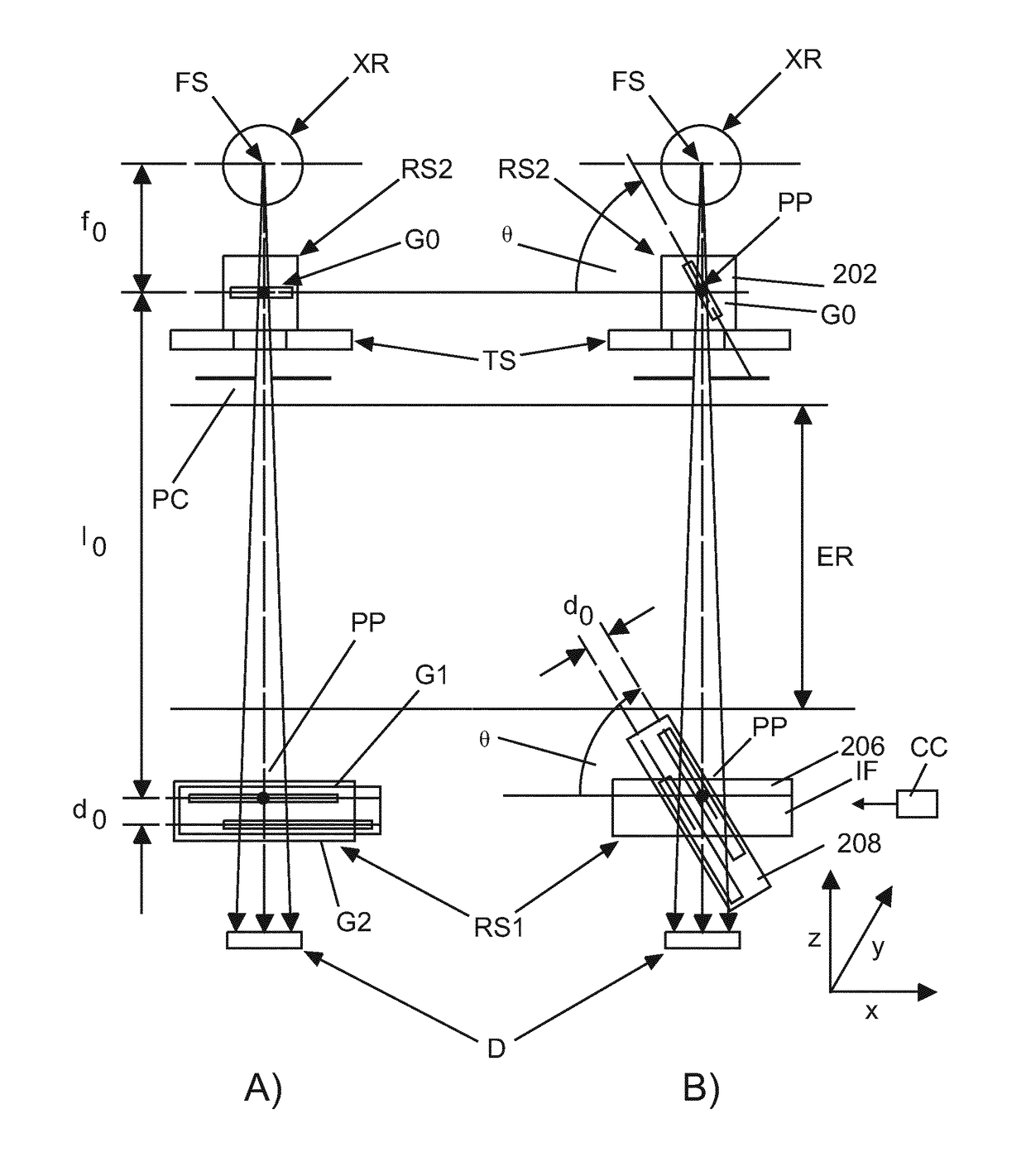
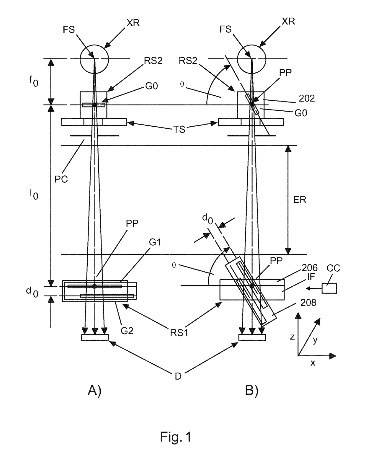
[0038]FIG. 1 affords two different side elevation views of an X-ray imaging apparatus at two different states shown in pane A and pane B respectively. The X-ray imaging apparatus comprises an X-ray source XR, a radiation sensitive detector D arranged across an examination region ER opposite said source XR. The examination region ER is configured to receive at least a part of an object OB to be imaged. Preferably, the X-ray source is operable at different voltages to produce X-radiation at different energies. The X-ray imaging apparatus further comprises an interferometer IF arranged between the X-ray source and the detector. In the following it will be convenient to introduce a reference frame of axis X, Y, and Z to better explain operation of the X-ray imaging apparatus as proposed herein. Axis X, Y define the image plane or plane of the field of view of the detector D. For instance, axis X, Y may be taken to extend, respectively, along two adjoining edges of the detector D. Perpen...


PUM


Abstract

A grating based interferometric X-ray imaging apparatus having an interferometer (IF). The interferometer comprises at least one grating (G1). The grating (G1) is tiltable relative to an optical axis of the X-ray imaging apparatus. This allows changing a design energy of the X-ray imaging apparatus.

Description

FIELD OF THE INVENTION[0001]The invention relates to an X-ray imaging apparatus, a method of operating an X-ray imaging apparatus, a computer program element, and a computer readable medium.BACKGROUND OF THE INVENTION[0002]Grating-based interferometric differential-phase contrast and dark-field imaging is a promising technology that adds diagnostic value in particular in the area of chest imaging since the dark-field signal channel is highly sensitive to changes of the micro-structure of lung tissue.[0003]However, adapting grating based interferometric imaging equipment to different imaging tasks is remarkably cumbersome at times. For instance, the adaptation may involve difficult and time consuming adjustments of an interferometer used in the imaging.SUMMARY OF THE INVENTION[0004]There may be a need for alternative X-ray imaging apparatuses.[0005]The object of the present invention is solved by the subject matter of the independent claims where further embodiments are incorporated ...

Claims


Application Information

Patent Timeline
IPC IPC(8): A61B6/00G02B5/18
CPCA61B6/4042A61B6/4291A61B6/482A61B6/484G02B5/1838A61B6/4241G21K1/10G21K2207/005A61B6/4035
Inventor MARTENS, GERHARDVAN STEVENDAAL, UDO
Owner KONINKLJIJKE PHILIPS NV
Why Eureka
Try Eureka