

Strain relieving valve assembly with flow blocking
- Summary
- Abstract
- Description
- Claims
- Application Information
AI Technical Summary
Benefits of technology
Problems solved by technology
Method used
Image

Examples
first embodiment
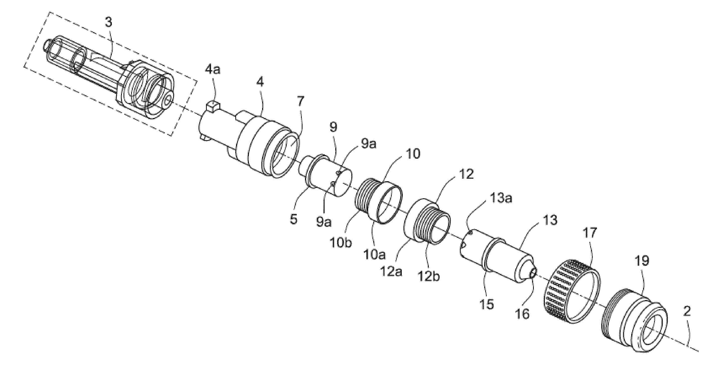
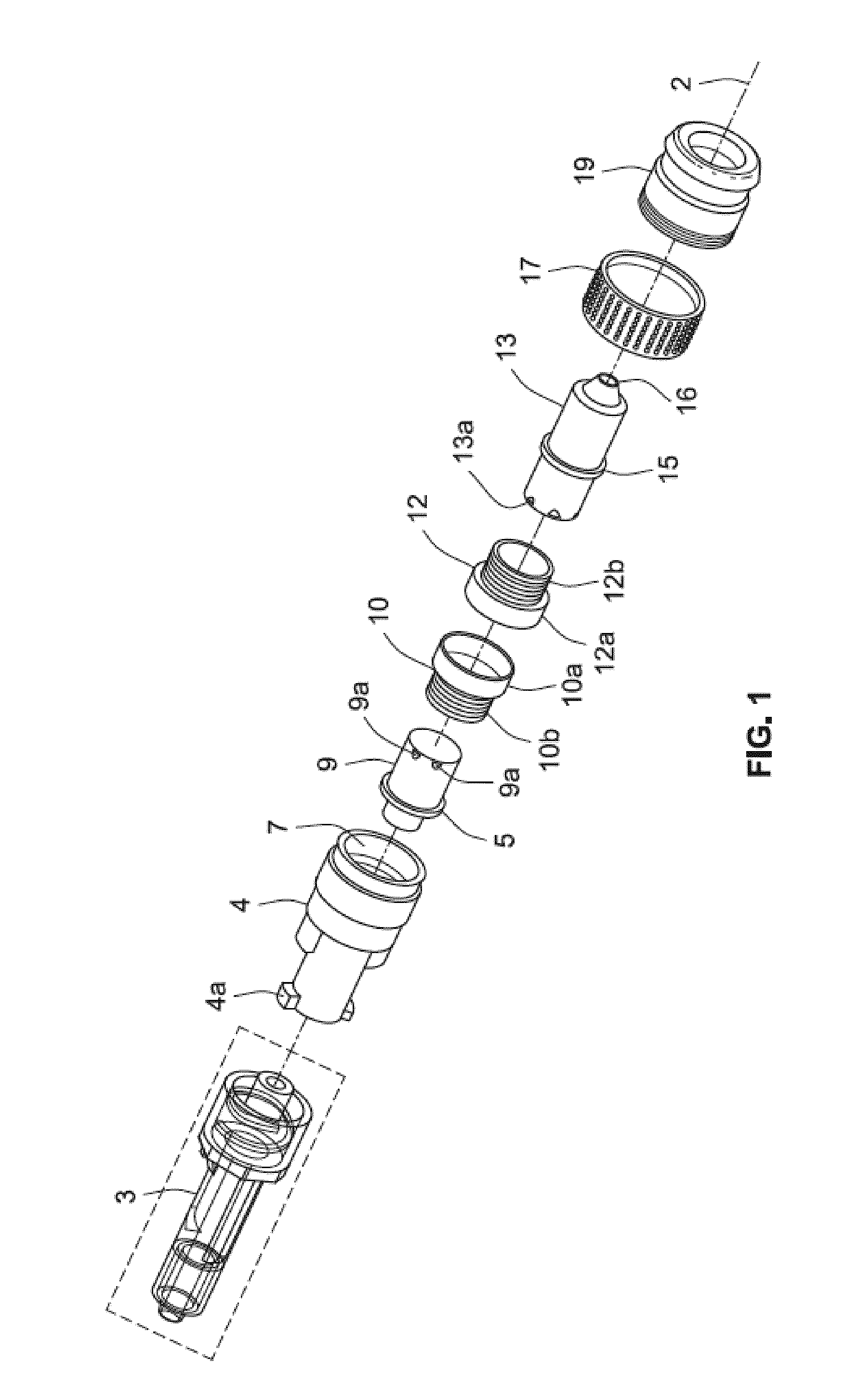
[0047]FIG. 1 illustrates a valve assembly 1 in accordance with the invention in an exploded perspective view. An adapter 3 does not form part of the present valve assembly 1 but may be integrated with a Venflon type of catheter (not shown) intended for coupling to a male socket arranged on the present valve assembly 1.
[0048]The valve assembly 1 comprises a first valve member or assembly comprising a first cylindrical housing member 4, a first hollow hub 9 and a first axially displaceable hollow member 10 or first hollow member 10. The valve assembly 1 comprises further a second valve member or assembly comprising a second cylindrical housing member 19, a second hollow hub 13 and a second axially displaceable hollow member 12. An inlet port (not shown) is formed in a distal end of the first cylindrical housing member 4 and a first coupling port 9a is formed in the first hollow hub 9. The inlet port is formed in a male socket 4a which is connectable to a mating female socket of the ex...
embodiment 1
[0064]In the detached coupling state of the valve assembly depicted in FIG. 4A, a first hollow member 12 is arranged in its distal position such that a solid annular section or ridge 12a thereof surrounds and tightly engages or covers the plurality of sideward facing openings 13a (refer to FIG. 1) blocking liquid flow through these. Liquid may flow through an axially extending flow path 34b of a first hollow hub 13 as indicated by the dotted arrow 34b but further flow is blocked at the plurality of sideward facing openings 13a by the solid annular ridge 12a. Thus, leakage of liquid from the first valve member at the first coupling port 13a is prevented in the detached state of the valve assembly 11 in a corresponding manner to the liquid flow blocking function described above in the first valve assembly embodiment 1. However, in the coupling member 11a, the liquid can flow between the an outlet port 33 and the oppositely arranged coupling port 9a in the detached coupling state due t...
second embodiment
[0067]FIG. 5 is an exploded perspective view a valve assembly 40 in accordance with the invention. The valve assembly 40 comprises a first valve member or assembly comprising a first hollow hub 41, a tubular sliding element 43, a first valve retaining element 44 and a first controllable valve comprising a half-portion of shared valve element 45. The valve assembly 40 comprises further a second valve member or assembly comprising a second valve retaining element 49, a second controllable valve comprising the residual or second half-portion of the shared valve element 45 and a tubular locking element 47. An inlet port (not shown) is formed in a distal end of the first hollow hub 41 having a cylindrical outer surface for press-fit coupling to a hollow delivery tube of mating shape. An outlet port 46 of the valve assembly 1 is arranged in an end section of the second valve retaining element 49. When the valve assembly 40 is placed in its engaged or attached coupling state, the assembly ...
PUM
 Abstract
Description
Claims
Application Information