Method for manufacturing a turbine assembly

a manufacturing method and turbine technology, applied in the direction of machines/engines, liquid fuel engines, forging/pressing/hammering apparatuses, etc., can solve the problems of increased cost, increased number of parts to handle, and increased cost, so as to reduce the loss of aerodynamic/performance, improve engine performance, and reduce the effect of cos

Inactive Publication Date: 2015-09-24
SIEMENS AG
View PDF7 Cites 2 Cited by
  • Summary
  • Abstract
  • Description
  • Claims
  • Application Information

AI Technical Summary

Benefits of technology

[0022]Moreover, a turbine assembly, which comprises at least two aerofoils that are arranged adjacent towards each other, manufactured according to the inventive method is provided. Due to the inventive matter a proper and reliable protection of the aerofoils of the turbine assembly can be provided. Moreover, uncertainties relating to the first processing technique within the unprocessed region—the Blind-spot region, may be minimised and advantageously be completely removed. Additionally, aerodynamic / performance losses can be minimised. This leads to an improved engine performance. With the use of such a turbine assembly, conventional state of the art precision castings of aerofoils, e.g. rotor blades and stator vanes, could be used by retrofitting existing components or implementing additional structures, for example. Hence, intricate and costly reconstruction of these aerofoils and changes to a casting process could be omitted. Consequently, an efficient turbine assembly or turbine, respectively, could advantageously be provided.
[0023]According to an embodiment the turbine assembly includes at least one twin aerofoil segment, which comprises the two adjacent aerofoils manufactured according to the inventive method, wherein one aerofoil comprises at least one cooling structure provided according to the second protection technique, and specifically the second heat protection technique. Hence, the twin aerofoils or even multiple aerofoils may be manufactured and / or processed in a single casting, resulting in possible cost savings, lower leakage flow and a more stable assembly as well as a reliable operation.
[0024]Advantageously, the other aerofoil lacks a cooling structure. In embodiments where all aerofoils and in an twin aerofoil segment both aerofoils are embodied with film cooling holes is this at an expanse of extra cooling consumption together with an associated aerodynamic loss. Thus, to provide only one aerofoil of the twin aerofoil segment or every second aerofoil in a turbine cascade or wheel with a cooling structure such factors may favourably be minimised. Moreover, such a non-periodic pattern or biased (film) cooling also minimises the number of cooling structures, e.g. film cooling holes, or the needed manufacturing equipment and / or time and thus saving on manufacturing costs.

Problems solved by technology

The effect of temperature on the turbine blades and / or stator vanes can be detrimental to the efficient operation of the turbine and can, in extreme circumstances, lead to distortion, oxidation and possible failure of the blade or vane.
This leads to a higher number of parts to handle and also increased cost.
When coating such a casting, using a so called line-of-sight coating approach the quality of the coating in some areas can be poor.
Problems arise in this approach when the aerofoils of the turbine assembly are arranged in such a way that specific regions of one or several aerofoils are covered or blocked by another aerofoil during the coating process.
This creates so-called Blind spots where local uncertainty with the coating quality and thickness may occur.
This may negatively affect the life and integrity of the component due to excessive temperature for the state of the surface or coating.

Method used


Image

  • Method for manufacturing a turbine assembly
  • Method for manufacturing a turbine assembly
  • Method for manufacturing a turbine assembly

Examples


Embodiment Construction

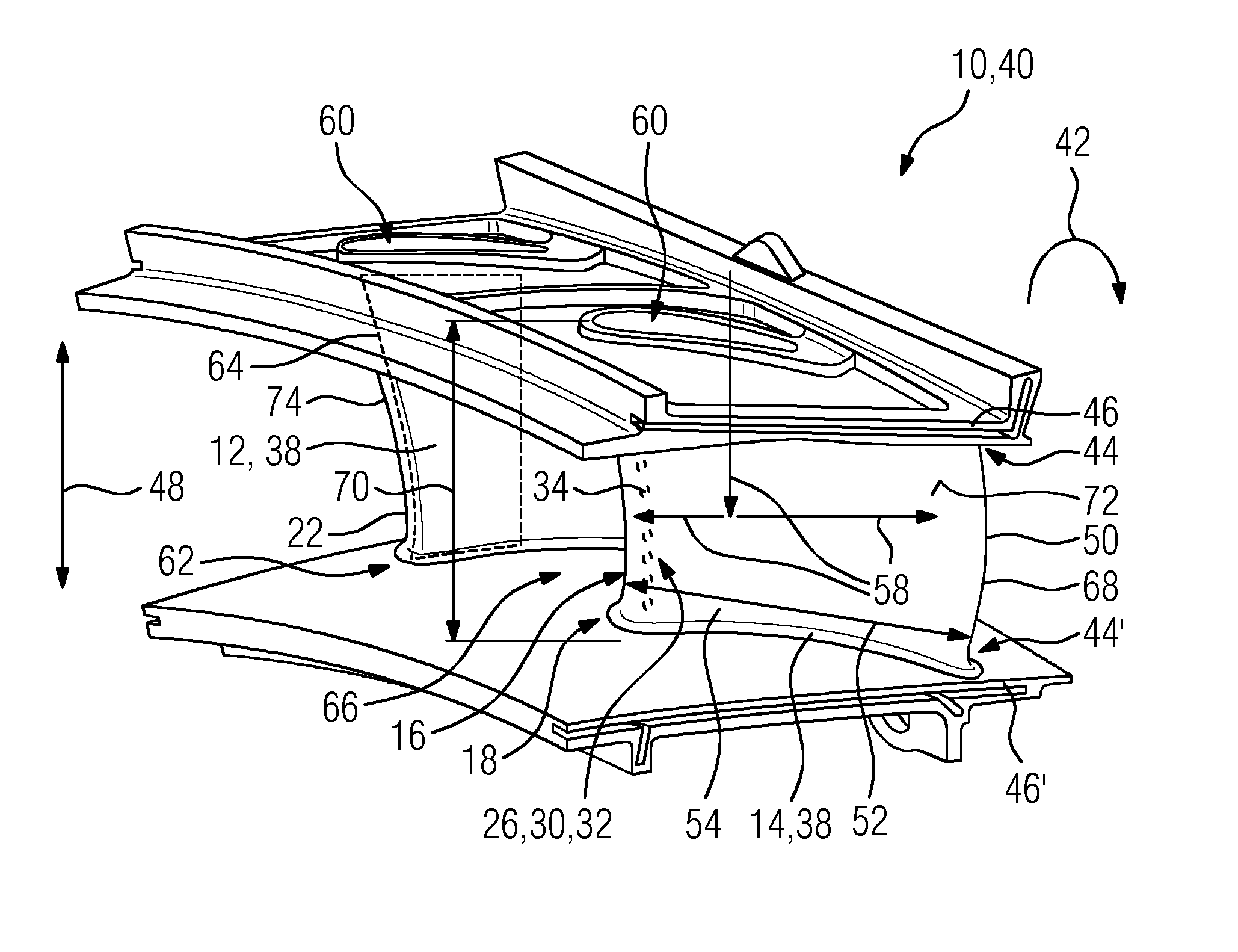
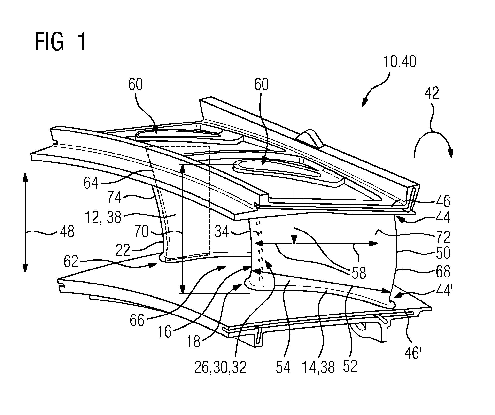
[0030]In the present description, reference will only be made to a twin aerofoil segment embodied as a double vane segment, for the sake of simplicity, but it is to be understood that the invention is applicable to both blades and vanes of a turbine.

[0031]FIG. 1 shows a perspective view of a turbine assembly 10. The turbine assembly 10 comprises a turbine cascade with a plurality of twin aerofoil segments 40 arranged one after the other in a circumferential direction 42 of the turbine cascade (not shown), wherein one twin aerofoil segment 40 is exemplarily shown in FIG. 1. A turbine assembly 10 or the twin aerofoil segment 40 comprises two aerofoils 12, 14 that are arranged in circumferential direction 42 adjacent towards each other. Thus, each aerofoil 12, 14 is embodied as a turbine vane 38. At two radial ends 44, 44′ of each aerofoil 12, 14, wherein the ends 44, 44′ are arranged opposed towards each other at the aerofoil 12, 14 an outer and an inner platform 46, 46′ are arranged....


PUM

PropertyMeasurementUnit
temperatureaaaaaaaaaa
thicknessaaaaaaaaaa
aerodynamic/performance lossesaaaaaaaaaa

Abstract

A method for manufacturing a turbine assembly, which includes at least two aerofoils arranged adjacent towards each other and embodied as a twin vane segment, is provided. The method includes: processing the turbine assembly with a first protection technique providing a first protection for the at least two adjacent aerofoils, wherein at least one region of one aerofoil remains unprocessed; pre-processing of the at least one region that will remain unprocessed or post-processing of the at least one region that remained unprocessed with a second protection technique to provide a second protection for the at least one region of the one aerofoil, wherein the first and the second protection techniques differ from one another.

Description

CROSS REFERENCE TO RELATED APPLICATIONS[0001]This application is the US National Stage of International Application No. PCT / EP2013 / 067527 filed Aug. 23, 2013, and claims the benefit thereof. The International Application claims the benefit of European Application No. EP12187429 filed Oct. 5, 2012. All of the applications are incorporated by reference herein in their entirety.FIELD OF THE INVENTION[0002]The present invention relates to a method for manufacturing a turbine assembly, which comprises at least two aerofoils that are arranged adjacent towards each other and to a turbine assembly for high temperature applications manufactured according to such a method.BACKGROUND TO THE INVENTION[0003]Modern gas turbines often operate at extremely high temperatures. The effect of temperature on the turbine blades and / or stator vanes can be detrimental to the efficient operation of the turbine and can, in extreme circumstances, lead to distortion, oxidation and possible failure of the blade...

Claims


Application Information

Patent Timeline
Patent Type & Authority Applications(United States)
IPC IPC(8): B23P15/02F01D5/14
CPCF01D5/147B23P15/02C23C4/00F01D5/186F01D9/041F01D5/288F05D2240/124F05D2240/121F05D2260/202Y10T29/49321
Inventor MUGGLESTONE, JONATHAN
Owner SIEMENS AG
Why Eureka
Try Eureka