Method for determining a distance between two nodes

a distance measurement and positioning solution technology, applied in the field of distance measurement and positioning solution enhancement, can solve the problems of large errors in a distance calculation, difficult to accurately measure the time of flight, time difference of arrival, etc., and achieve the effect of accurate time stamping and accurate time stamping

Active Publication Date: 2020-09-03
NIDA TECH SWEDEN
View PDF0 Cites 1 Cited by
  • Summary
  • Abstract
  • Description
  • Claims
  • Application Information

AI Technical Summary

Benefits of technology

[0008]An object of the present invention is to enable accurate time stamping in a positioning and/or distance determining system for short and medium short distances, i.e. about 0 to 1.000 m

Problems solved by technology

Having a time of flight between two devices that also is in the range nanoseconds will lead to considerable errors due to the poor resolution of the time stamp.
However, with the clock frequencies available today it is difficult to accurately measure time of flight, time difference of arrival, and similar solutions due to the fact that even very small errors in the time measurements, due to the poor resolution of the time stamps, translate into large errors in a distance calculation or positioning determination.
Further, higher clock frequencies in general consumes more energy and for small

Method used


Image

  • Method for determining a distance between two nodes
  • Method for determining a distance between two nodes
  • Method for determining a distance between two nodes

Examples


Embodiment Construction

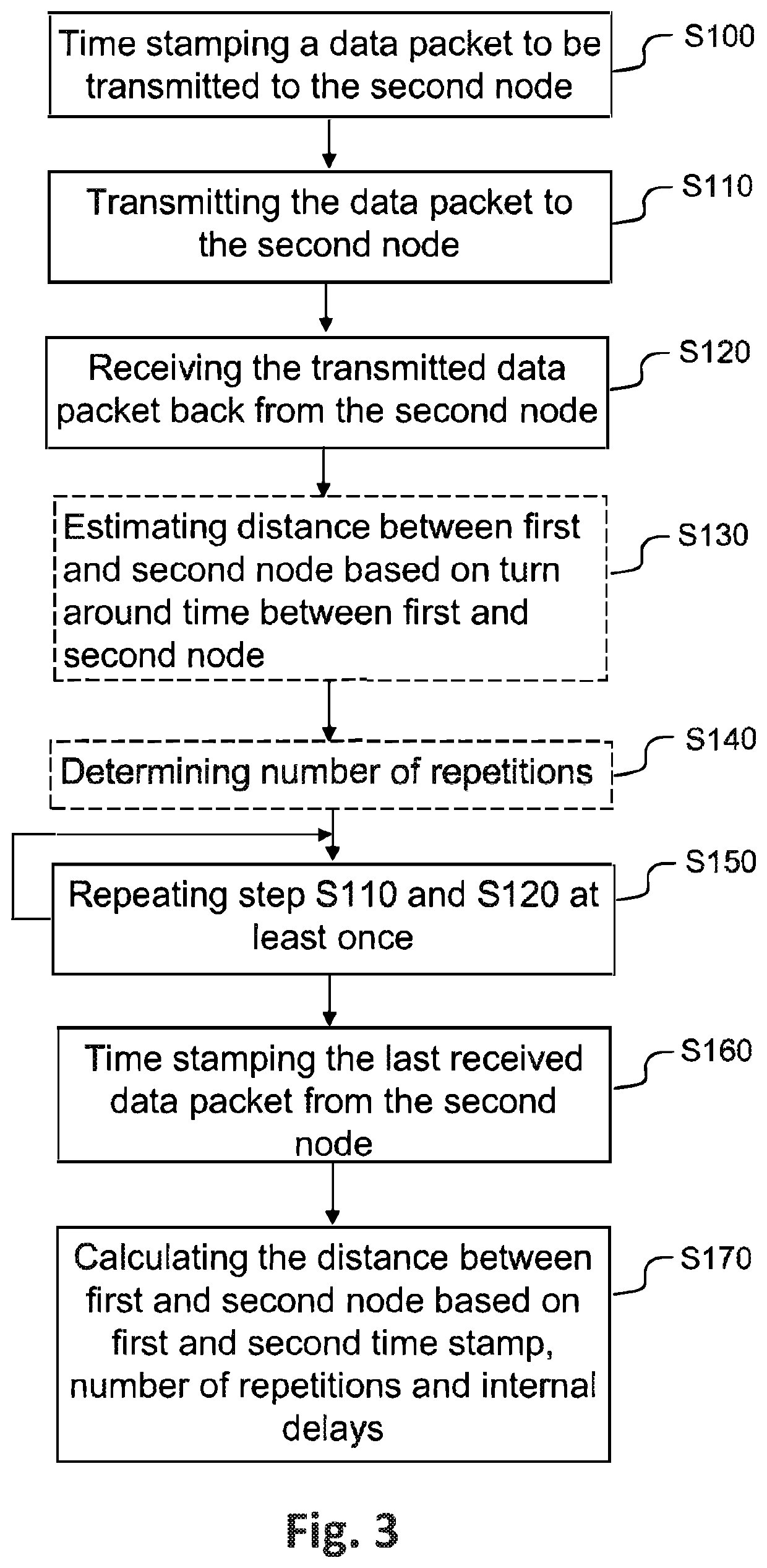
[0029]In the following, a detailed description of the method performed by a first node for determining a distance between the first and a second node will be made.

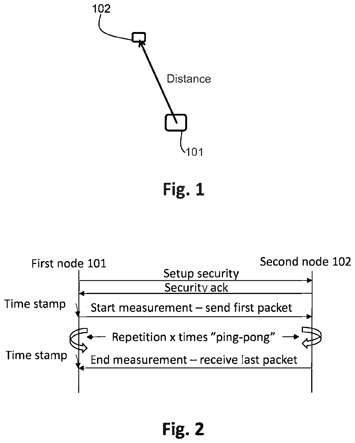
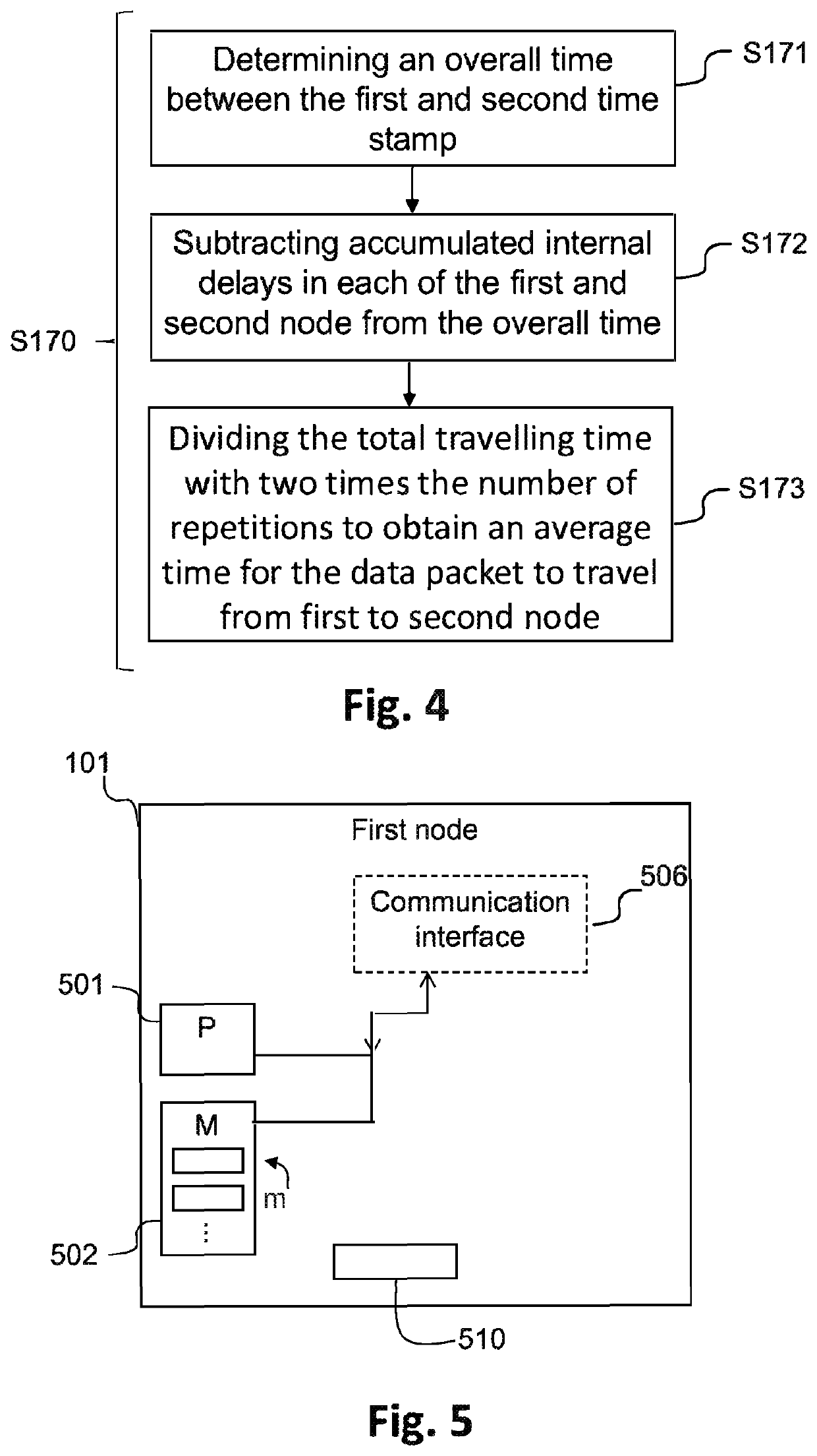
[0030]FIG. 1 is a general view of a scenario showing the first node 101 and the second node 102. It is the distance between these two nodes 101, 102 that is to be determined. The first node 101 may for example be a User Equipment, UE such as a mobile phone, smart phone, PDA, tablet, PC, laptop or similar or it can be a dedicated locator device used for locating and determining the distance to a second node 102. An exemplary first node 101 will be described closer in conjunction with FIG. 5. The second node 102 may also be a UE as the first node 101, but could also be a more passive device comprising a radio frequency transceiver. At some time, a user wants to determine the distance to or locate the second node 102. Examples of such an occasion can be, without limitation, when the object has been stolen, lost, or when a per...


PUM


Abstract

The present invention relates to a method and a first node for performing the method of determining a distance between the first and a second node. The method comprises time stamping a data packet to be transmitted from the first node to the second node with a first time stamp, transmitting said data packet to the second node, receiving the transmitted data packet back from the second node, repeating the transmitting and receiving step at least one more time, time stamping the last received data packet from the second node with a second time stamp, and calculating the distance between the first and second node based on the first and second time stamp, the number of repetitions of the repeating step and the internal delays in the first and second node.

Description

TECHNICAL FIELD[0001]The present invention relates generally to an enhanced time stamping method for distance measurements and positioning solutions and a node for performing such distance measurements.BACKGROUND ART[0002]When determining the distance between two devices one may measure the time it takes for a signal travelling between the devices. One way is to time stamp the signal when it leaves one device and when it arrives at another device and then use the time difference between the time stamps to calculate the distance in between. The accuracy or resolution of time stamping is highly dependent on clock frequencies in the nodes and on transmission frequencies. Higher clock and transmission frequencies increase the resolution of the timing. If you for example use a clock frequency of 40 Mhz, the shortest possible time between two time stamps is 25 nanoseconds. Having a time of flight between two devices that also is in the range nanoseconds will lead to considerable errors du...

Claims


Application Information

Patent Timeline
IPC IPC(8): G01S13/76H04L12/26
CPCH04L43/067G01S13/762G01S13/767G01S13/765G01S5/14G01S5/0295H04L43/0864H04W64/003G01S13/74
Inventor DACKEFJORD, HÅKANTAWS, WARWICK
Owner NIDA TECH SWEDEN
Why Eureka
Try Eureka