
Slot cutting apparatus

Inactive Publication Date: 2008-08-28
DIAMOND SURFACE
View PDF72 Cites 12 Cited by
  • Summary
  • Abstract
  • Description
  • Claims
  • Application Information

AI Technical Summary

Benefits of technology

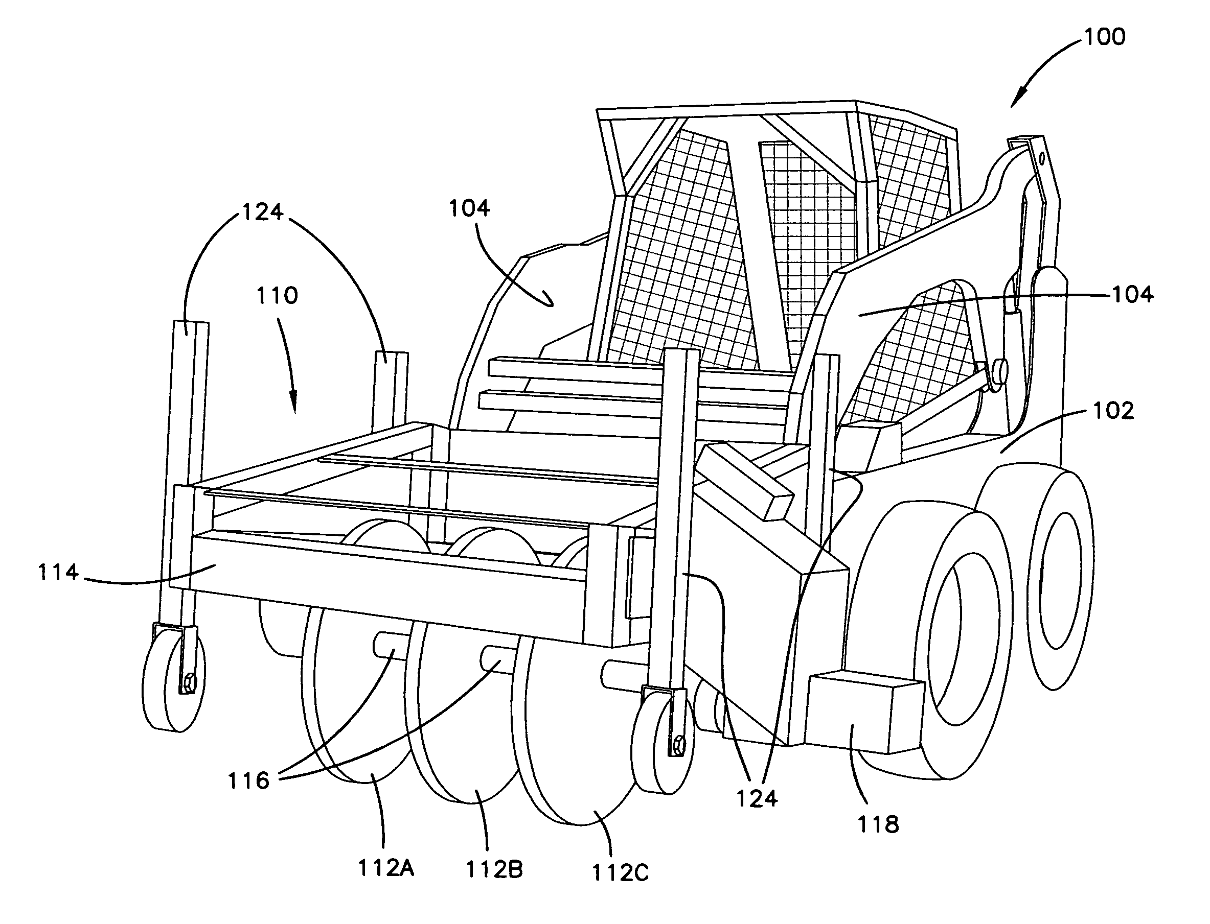
[0010]The present invention is directed to a system and method for cutting joint reinforcement recesses in pavement. The system includes a first cutting apparatus on a first vehicle for cutting sides of slots or recesses and a second cutting apparatus on a second cutting vehicle for removing material between the opposed cut sides of the recesses. The first vehicle is a large, heavy vehicle and includes a frame body and wheels driven by an engine. The engine provides power to various systems and a cab includes controls for the various vehicle systems and allows the operator a clear view of the cutting operation from one location. In one embodiment, the vehicle also includes a lift system to raise the vehicle for precise cutting providing back and forth movement along rails associated with the lift system.
[0014]The second cutting assembly also includes depth adjustment mechanisms that allow for presetting the depth to which the blades extend for making the cuts into the pavement. The blades are spaced apart at the same distance as the sides of the slots so that the blades align with the previously cut sides to mill the entire width of the recess. The cuts are made by simply lowering the blades to engage the pavement between the precut sides of the slots. The vehicle is moved back and forth and moved to a sufficient depth until material between the sides is removed and the slots have been formed to the proper depth. The present invention provides for making the precise cut to a predetermined depth providing for a bottom recess that is substantially parallel to the surface of the pavement for correct spacing of the pavement joint support systems including the dowel and the chairs. The blades widths and depth adjustment mechanisms ensure that the slots are made to a consistent depth and width for receiving the support assemblies known as chairs and properly positioning the chairs for optimal performance.

Problems solved by technology

It can be appreciated that milling and sawing pavement is a difficult and expensive operation.
Blades can become quickly worn and substantial power is required for such operations.
Milling such wide slots is especially difficult due to the power needed.
Moreover, as the amount of material and depth to which the slot must be milled is large, the blades of the grinder wear so quickly that they must be replaced typically after only three or four slots have been milled.
Such procedures are inefficient and are time and cost prohibitive.
The use of jackhammers does not provide a consistent depth or smooth sides that provide superior performance for a reinforcing joint.
Such an operation is time consuming and involves high manual labor costs.

Method used


Image

  • Slot cutting apparatus
  • Slot cutting apparatus
  • Slot cutting apparatus

Examples


Embodiment Construction

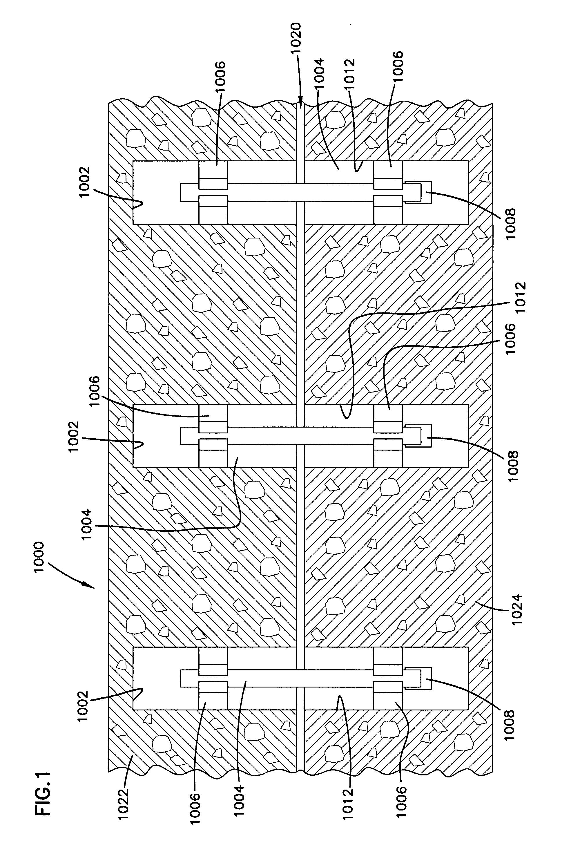
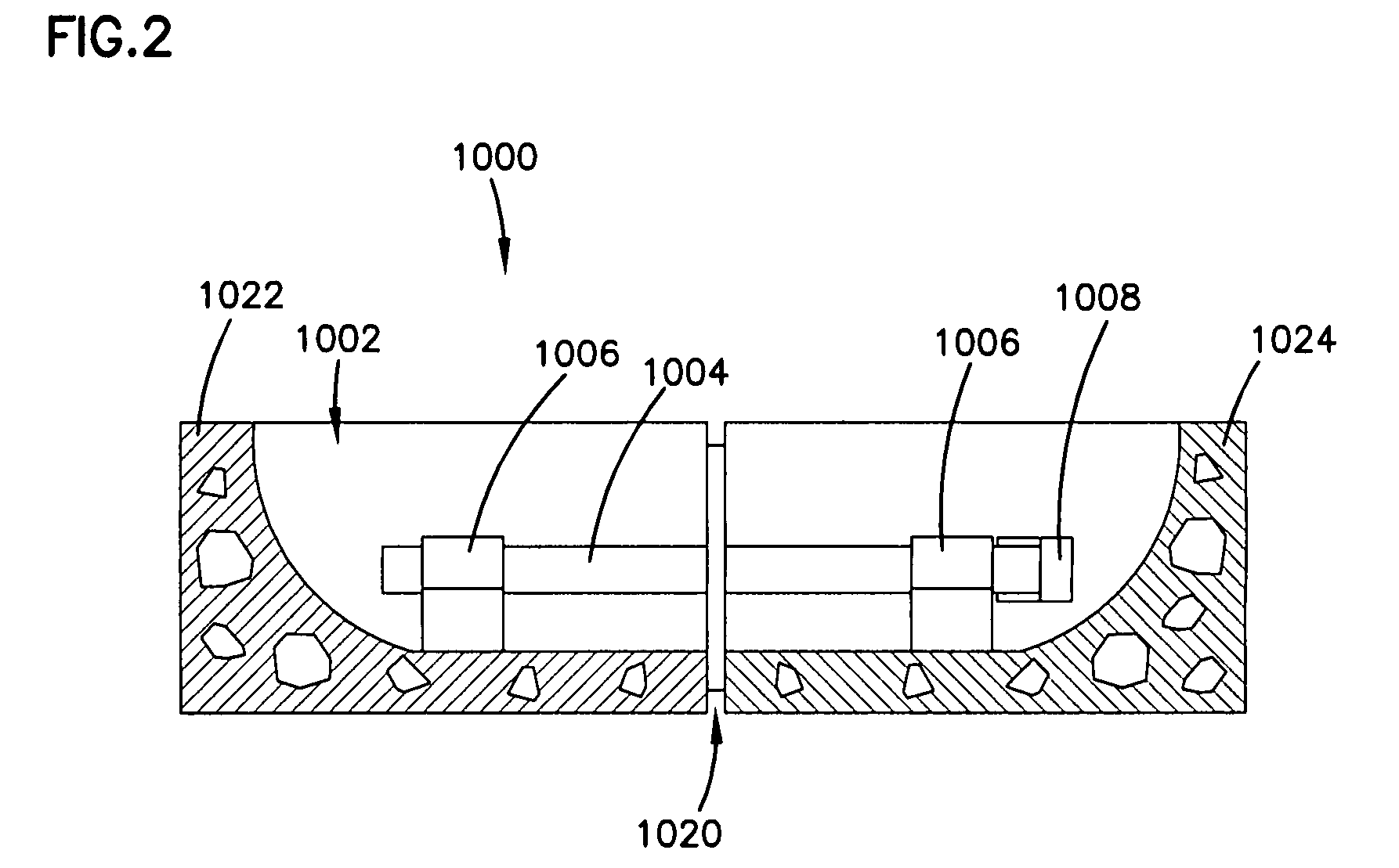
[0028]Referring now to the drawings and in particular to FIGS. 1-4, pavement reinforcing systems, generally designated 1000, are placed in recesses or slots 1002 as shown in FIG. 1, which are refilled to be level with the road surface. Such conventional reinforcing devices 1000 and techniques are well known in the art and utilize a dowel 1004 or other structure anchored at each end extending across a pavement joint 1020. The dowel 1004 is generally supported above the bottom of the recess 1002 by supports 1006, commonly known as chairs. Fill material, such as concrete, is deposited in the recess 1002 and flows around the dowel 1004 to securely anchor it to the pavement sections 1022 and 1024. The dowel may include an end cap 1008 on one or both ends of the dowel 1004. The reinforcement systems 1000 anchor and support the pavement 1022 and 1024 across the joint 1020 during expansion and contraction and strengthen the pavement 1022 and 1024 proximate the joint 1020.

[0029]Referring to ...


PUM


Abstract

A system for cutting slots in pavement has a first slot cutting vehicle with a cutting assembly having several pairs of rotating blades mounted to the first vehicle and vertically adjustable relative to the vehicle. A lift system moves the first vehicle between a first position wherein the lift is not engaging the ground and a raised position wherein the lift engages the ground and supports the vehicle. A slider assembly uses a hydraulic ram to move the vehicle horizontally on rails relative to the lift when the vehicle is at the raised position. In operation, the vehicle is lifted and the cutting assembly lowered so the blades engage the pavement. The vehicle slides back and forth so the blades cut opposed pairs of sides of slots. Material between each slot is removed with a second cutting vehicle having a cutting assembly with radial blades spaced the same distance apart as the blade pairs of the first vehicle. The blades of the second cutting vehicle have a width equal to the distance between the pairs of blades on the first cutting vehicle to remove material between the cut sides of the slots.

Description

BACKGROUND OF THE INVENTION[0001]1. Field of the Invention[0002]The present invention is directed to a method and apparatus for cutting slots in pavement and in particular to a method and apparatus for cutting slots for reinforcement devices that are inserted to reinforce pavement joints.[0003]2. Description of the Prior Art[0004]Roads and other pavement surfaces are conventionally constructed with joints formed for expansion and contraction. To strengthen such joints, reinforcement dowels are inserted beneath the surface of the pavement and spanning the joint to anchor both sections of the pavement. These reinforcement assemblies are located at spaced intervals extending across the width of the road the normal tire travel paths. These locations are commonly known as load transfer restoration locations. Three dowels are typically spaced at intervals along the joint at each tire travel path. The reinforcing structure typically includes a slot formed in the pavement with a reinforcing...

Claims


Application Information

Patent Timeline
IPC IPC(8): E01C23/02B62D11/02E21C25/00
CPCE01C23/088E01C2301/50E01C23/0946E01C23/0933
Inventor KRAEMER, TERRENCE L.
Owner DIAMOND SURFACE
Learn More