Eureka AIR delivers breakthrough ideas for toughest innovation challenges, trusted by R&D personnel around the world.

Low cost torque vectoring system

Inactive Publication Date: 2008-08-28
GM GLOBAL TECH OPERATIONS LLC
View PDF7 Cites 15 Cited by
  • Summary
  • Abstract
  • Description
  • Claims
  • Application Information

AI Technical Summary

Benefits of technology

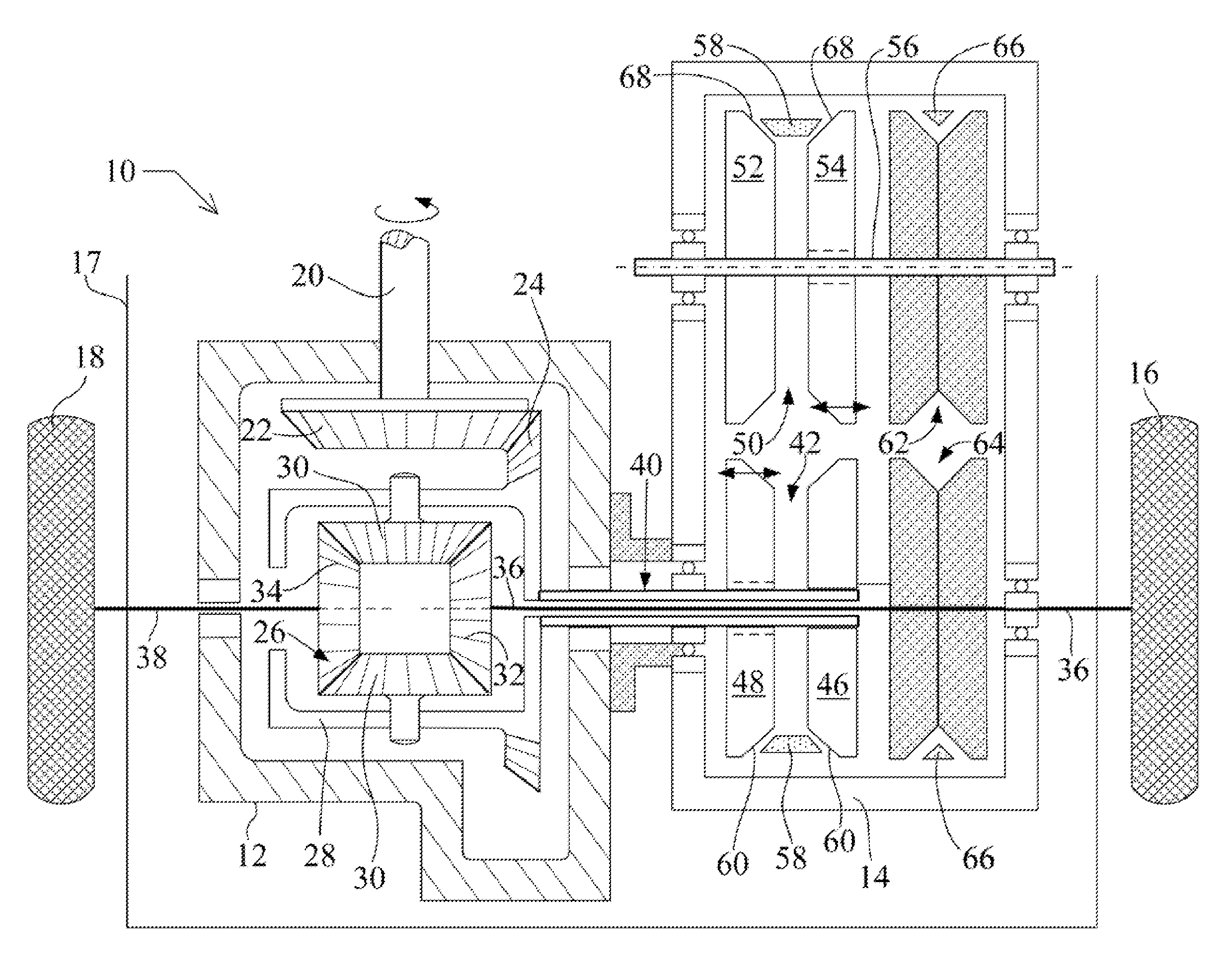
[0006]According to one aspect of the invention, the continuously variable transmission (CVT) is a belt driven system having a plurality of pulleys having adjustable walls or sheave portions to provide a variable and adjustable effective pulley drive radius. The CVT includes a variable width drive pulley driveably coupled to the CVT input shaft. The variable width drive pulley has two spaced confronting beveled walls for confining and frictionally engaging a drive belt there between. The spacing between the beveled walls is variable to adjustably effect the belt drive radius of the drive pulley. The CVT further includes a variable width driven pulley. The driven pulley has two spaced confronting beveled walls for confining and frictionally engaging the d

Problems solved by technology

A significant limitation of currently available torque vectoring systems is the cost of the mechanical components making up the torque vectoring system.
The relatively high prices of currently available torque vectoring systems limits the application of torque vectoring technology to premium motor vehicles where the cost of such systems can be covered in the sticker price.

Method used


Image

  • Low cost torque vectoring system
  • Low cost torque vectoring system

Examples


Embodiment Construction

[0012]Referring to FIG. 1, the torque vectoring drive system 10 has as its main components a conventional motor vehicle differential unit 12 driveably coupled to a continuously variable transmission (CVT) 14. The combination of the differential unit 12 and the continuously variable transmission 14 provides an active over drive or under drive to the first driven wheel 16 of a motor vehicle 17.

[0013]Power is supplied to the pinion gear 22 by the drive shaft 20 powered by the motor vehicle engine (not shown), transmission (not shown) and other drive train components. The pinion gear 22 meshably engages the bevel gear 24 via meshing of the gear teeth of the pinion gear 22 and bevel gear 24. The carrier 28 is secured to or is part of the bevel gear 24 so that the carrier 28 rotates as a unit with the bevel gear 24. A plurality of planetary gears forming a differential gear assembly 26 is positioned within the carrier 28. Two opposing planetary gears 30 of the differential gear assembly 2...


PUM


Abstract

A torque vectoring drive system is presented for use in a motor vehicle. The torque vectoring drive system includes a differential unit having an input shaft, a first axle shaft, a second axle shaft, and a carrier, the differential rotatably driving the axle shafts while permitting the axle shafts to have independent speeds of rotation. The system includes a continuously variable transmission (CVT) having an input shaft driveably coupled to the carrier of the differential and an output shaft driveably coupled to the first axle shaft of the differential. The CVT is operable to variably control the drive torque of the first axle shaft relative to the second axle shaft to provide torque vectoring.

Description

TECHNICAL FIELD[0001]This application relates to differentials, drive axles and drive train assemblies for transmitting motive power to the driven wheels of motor vehicles and, more particularly, to drive axles equipped with a torque vectoring drive system for selectively allocating or vectoring available drive torque between the driven wheels of a motor vehicle.BACKGROUND OF THE INVENTION[0002]It is known to apply torque vectoring drive systems on motor vehicles, such as motor vehicles utilizing applications using AWD (all wheel drive) technology. AWD drive provides well recognized advantages to motor vehicle traction and handling in foul-weather conditions (both on and off-road).[0003]Torque vectoring is the practice of enabling the motor vehicle driveline to selectively and dynamically increase the rotational speed of one driven axle relative to an opposing second driven axle to enhance vehicle handling and cornering. The effect is similar to the effect of stability control syste...

Claims


Application Information

Patent Timeline
IPC IPC(8): F16H9/12F16G1/00F16H63/06
CPCB60K17/16F16H2009/166F16H48/20F16H48/08
Inventor MAGUIRE, JOEL M.
Owner GM GLOBAL TECH OPERATIONS LLC
Why Eureka
Eureka Blog
Learn More