Eureka AIR delivers breakthrough ideas for toughest innovation challenges, trusted by R&D personnel around the world.

Torque vectoring system

a technology of torque vectoring and differential design, applied in mechanical equipment, transportation and packaging, gearing, etc., can solve the problems of preventing significant torque from being developed on either axle, similar disadvantages, and too many limitations

Inactive Publication Date: 2008-07-24
BORGWARNER INC
View PDF53 Cites 13 Cited by
  • Summary
  • Abstract
  • Description
  • Claims
  • Application Information

AI Technical Summary

Benefits of technology

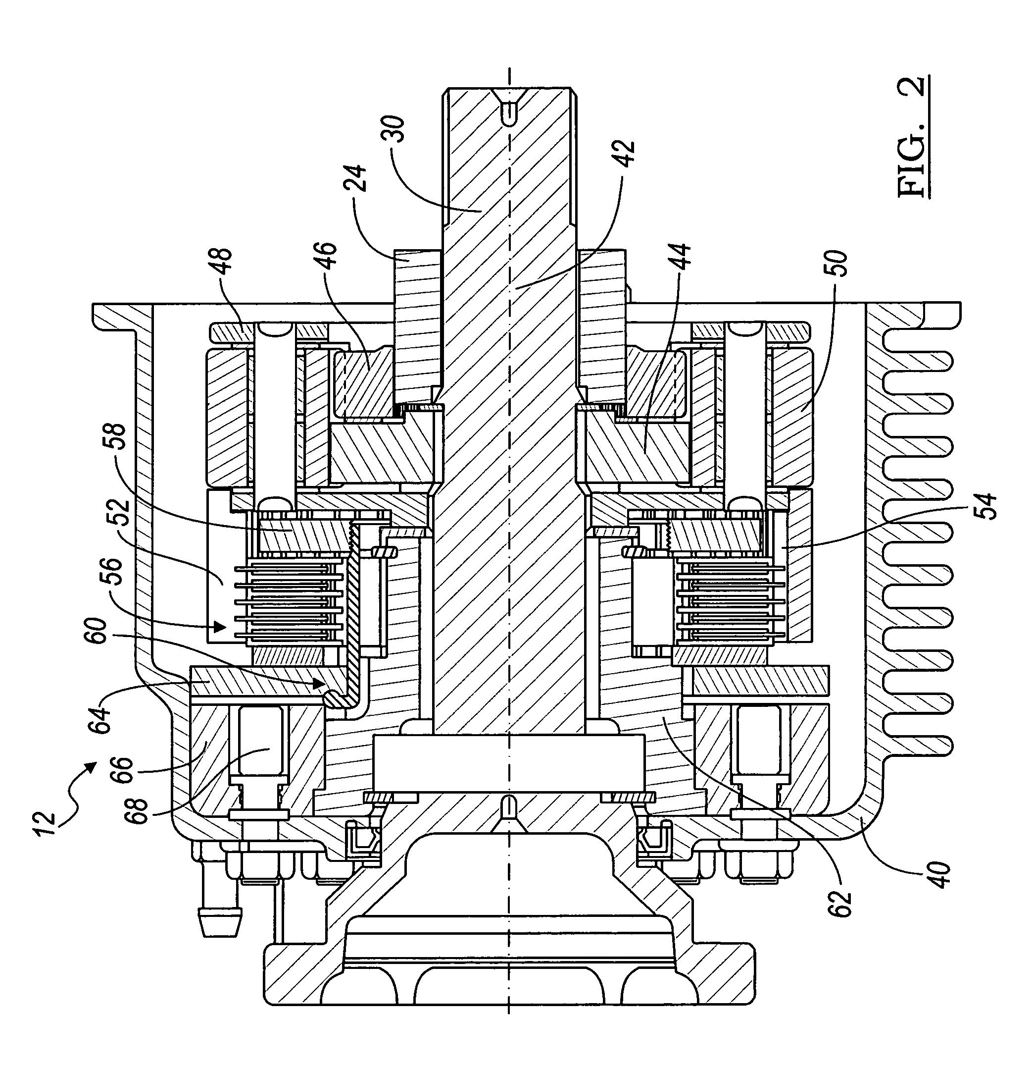
[0006]This invention relates to a system for a torque vectoring differential in motor vehicle applications. The system allows for overdriving or underdriving of a wheel by using a clutch to control torque and speed generated between the differential carrier and the wheel. The system includes a shaft, a first gear, a second gear, a carrier and a set of planet gears. The first gear engages and rotates together with the shaft. The second gear engages and rotates together with the differential carrier. Both the first and second gear both rotate about the shaft central axis and engage the set of planet gears thereby forming a gear ratio between the first and second gear other than one. For example, the first gear may have more teeth than the second gear. Each of the planet gears are housed in the carrier about the first and second gear. The carrier rotates about the shaft central axis and locates the planet gears about the circumference of the carrier to engage both the first and second gears. The carrier also includes an extended portion with teeth about an inner circumference to engage a clutch pack. In a normal mode of operation, the carrier, the first gear, and the second gear all rotate about the shaft at shaft speed. However, in an torque vectoring mode, the clutch pack is compressed transferring torque from the carrier to a mechanical ground. As such, the carrier and the second gear rotate at a variable speed based on the torque transferred through the clutch pack.

Problems solved by technology

The earliest and most basic designs of differentials are known as open differentials in that they provide equal torque between the two half-shafts and do not operate to control the relative rotational speeds of the axle shafts.
A well known disadvantage of open differentials occurs when one of the driven wheels engages the road surface with a low coefficient of friction (μ) with the other having a higher μ. In such case, the low tractive force developed at the low μ contact surface prevents significant torque from being developed on either axle.
Similar disadvantages occur in dynamic conditions when operating, especially in low μ or so-called split μ driving conditions.
Although the above described locking and limited slip differential systems provide significant benefits over open differentials in many operating conditions, they too have significant limitations.
Reliability and warranty problems are issues with many locking differential designs.
Locking differentials using a mechanical friction interface are subject to wear of the friction materials.
These locking and limited slip differential systems can only remove driving torque from the faster axle half-shaft and add it to the slower axle half-shaft.
These systems, however, only operate in an energy dampening (i.e. braking) mode.

Method used


Image

  • Torque vectoring system
  • Torque vectoring system
  • Torque vectoring system

Examples


Embodiment Construction

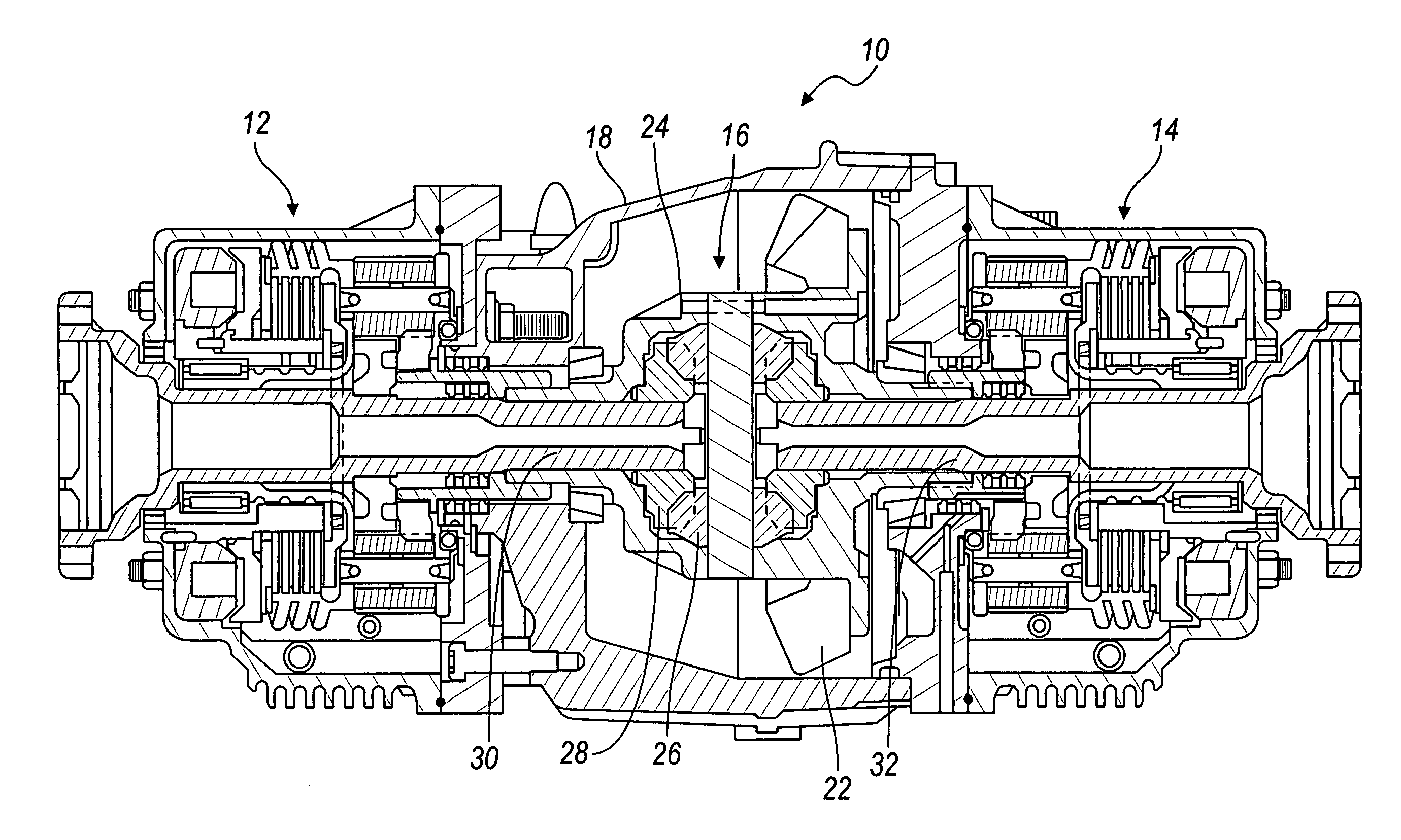
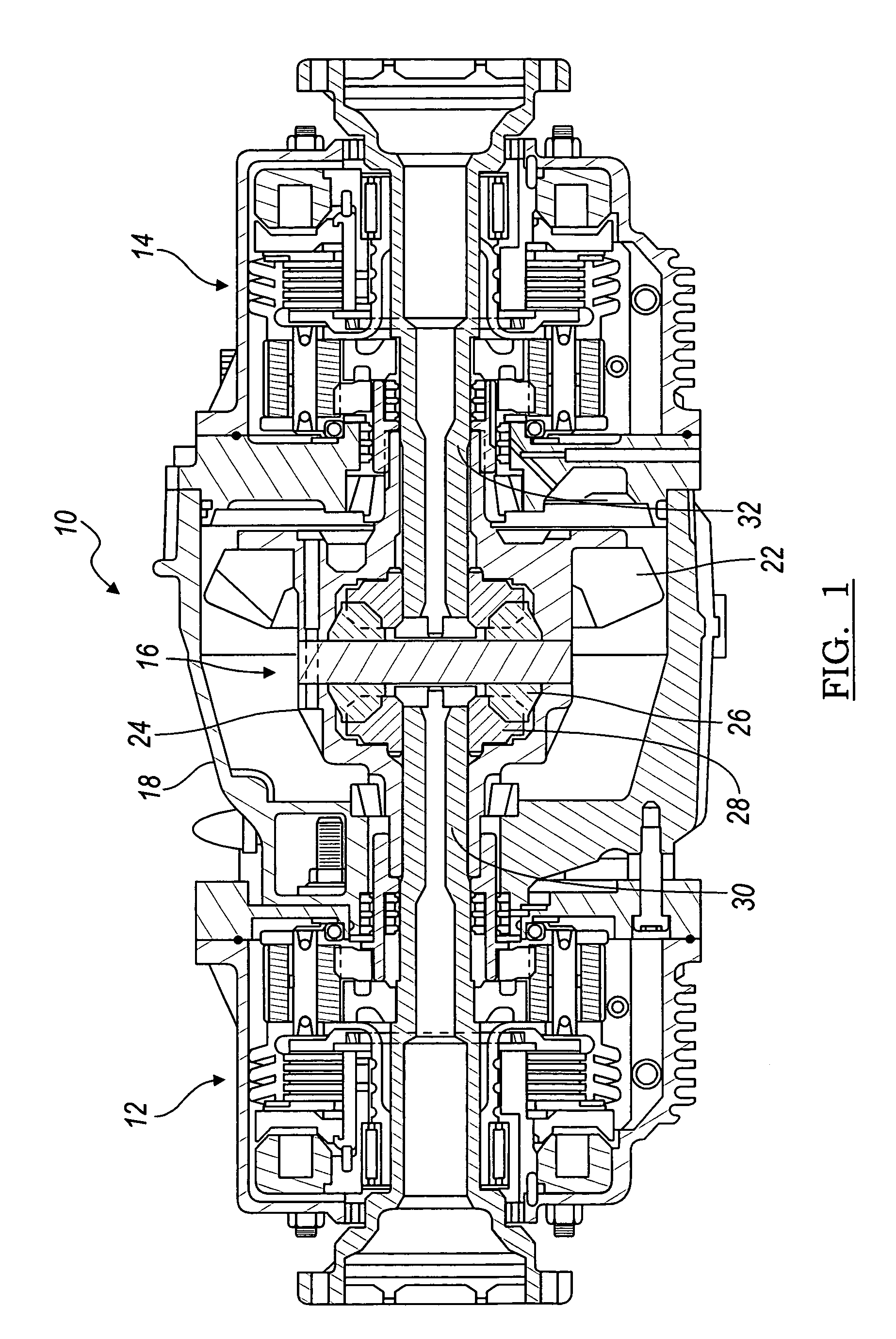
[0023]A torque vectoring differential system is shown in FIG. 1 and is generally designated by reference number 10. The basic components of system 10 include a left torque vectoring assembly 12, a right torque vectoring assembly 14, and differential gear assembly 16. The basic mechanical features of the differential assembly 16 will be described followed by a description of the torque vectoring assemblies 12, 14.

[0024]Differential assembly 16 shown in FIG. 1 includes basic elements of typical differential assemblies, which include ring gear 22 which is driven by a hypoid or bevel gear pinion (not shown) coupled with the vehicle's propeller shaft. Ring gear 22 is coupled with differential carrier 24 which rotates with the ring gear 22. Two or more pinion gears 26 are rotatable about a common differential shaft mounted to the carrier. Pinion gears 26 mesh with a pair of side gears 28 which are in turn splined or otherwise connected with a pair of shafts 30 for the left and right hand ...


PUM


Abstract

A system for a torque vectoring differential in motor vehicle applications is provided. The system includes a shaft (30), a first gear (44), a second gear (46), and a set of planet gears (50). The first gear (44) engages and rotates together with the shaft (30). The first and second gear (44, 46) both engage the set of planet gears (50) thereby forming a gear ratio between the first and second gear (44, 46) other than one. A carrier (48) rotates about the shaft central axis (42) and locates the planet gears (50) about the circumference of the carrier (48) to engage both the first and second gears (44, 46). In a normal mode of operation, the carrier (48), the first gear (44), and the second gear (46) all rotate about the shaft (30) at shaft speed. However, in an enhanced torque mode, the clutch pack (56) is compressed transferring torque from the carrier (48) to a mechanical ground (62).

Description

FIELD OF THE INVENTION[0001]This invention relates to a system for a motor vehicle differential design which provides axle torque vectoring capabilities.BACKGROUND OF THE INVENTION[0002]Conventional rear-wheel drive motor vehicles provide wheel driving torque through a propeller shaft coupled through a differential to left and right half-shafts. Front-wheel drive vehicles couple to front wheel drive half-shafts through a differential driven by a transaxle. Normally, four-wheel drive and so-called all-wheel drive vehicles also use differentials to drive front and rear axles. Rear wheel drive vehicles also use a differential to drive the rear half shafts. Differentials allow differences in wheel rotational speed to occur between the left and right side driven half-shafts (and between front and rear axles in some applications). The earliest and most basic designs of differentials are known as open differentials in that they provide equal torque between the two half-shafts and do not op...

Claims


Application Information

Patent Timeline
Patent Type & Authority Applications(United States)
IPC IPC(8): F16H48/22F16H37/08
CPCB60K17/16F16H48/08F16H48/11F16H2048/346F16H48/30F16H48/34F16H2048/204F16H48/22
Inventor SHOWALTER, DAN J.
Owner BORGWARNER INC
Why Eureka
Eureka Blog
Learn More