
Manual breast pump

a breast pump and manual technology, applied in the field of manual breast pump, can solve the problems of inconvenient hand extension of the hand, insufficient comfort and ease of use of the breast pump system, and inconvenient use of the pump handl

Inactive Publication Date: 2008-08-28
PLAYTEX PROD INC
View PDF99 Cites 31 Cited by
  • Summary
  • Abstract
  • Description
  • Claims
  • Application Information

AI Technical Summary

Benefits of technology

[0008]The present disclosure provides a manual breast pump that is ergonomically designed to provide comfort and ease of use.
[0010]A method for producing a massaging action on a breast to assist in the expression of breast milk while using a breast pump is also provided. The breast pump includes a housing, a cup, a flexible insert, and a pressure source. The method comprises: forming an isolated air volume between the flexible insert and the cup, and using the pressure source to reciprocally apply and release a negative pressure within the housing. The application of the negative pressure causes the isolated air volume to expand and the flexible member to move toward the breast and apply a massaging action, and the release of the negative pressure causes the isolated air volume to contract and move away from the breast.
[0011]The present disclosure further provides a manual breast pump that avoids excessive noise and vibrations.

Problems solved by technology

Previous manual breast pump systems do not provide sufficient comfort and ease of use.
Previous pumps have pump handles that are not ergonomically designed to fit a woman's hand, especially those women with small hands.
Previous breast pump designs often require the woman to extend her hand in an uncomfortable manner.
After repeated cycles of pumping, such designs can result in prolonged discomfort and lingering pain in the user's hand.
Previous manual breast pump systems further fail to facilitate cleaning of the devices through use of easily separable components.
Additionally, previous manual breast pumps often create excess noise and vibrations that are annoying to a user, may cause further discomfort, and prevent the user from using the breast pump discretely.

Method used


Image

  • Manual breast pump
  • Manual breast pump
  • Manual breast pump

Examples


Embodiment Construction

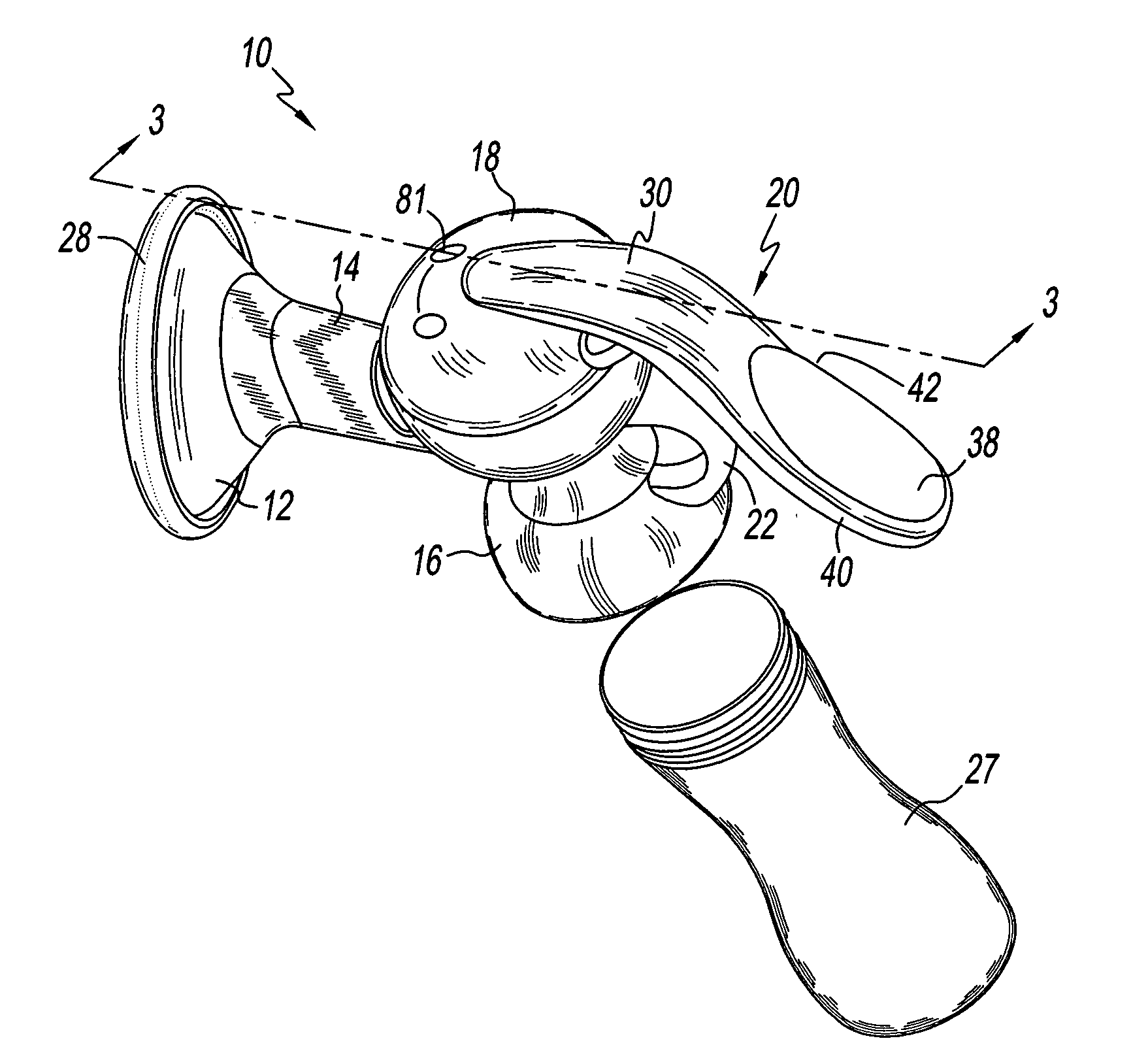
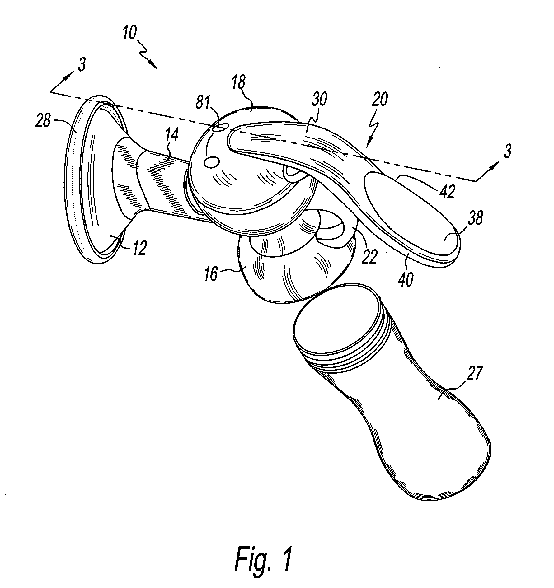
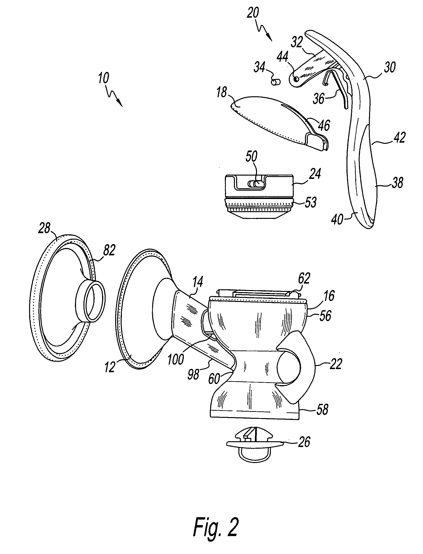
[0021]Referring to the drawings and in particular, to FIGS. 1 through 3, there is provided a manual breast pump generally represented by reference numeral 10. Breast pump 10 includes a cup 12, a funnel 14, a housing 16, a lid 18, a handle assembly 20 and a finger grip 22. Handle assembly 30 is pivotably connected to lid 18, and a piston 24 is connected to handle assembly 20 and movably positioned within housing 16. A valve 26 is located at a lower end of housing 16, and an insert 28 is securably positioned within cup 12. A receptacle 27 for receiving milk pumped from the breast of a user is removable connected to housing 16.

[0022]Handle assembly 20 includes handle 30, lever 32, pin 34, and spring 36. Spring 36 connects lid 18 with handle assembly 20. In the embodiment shown, handle 30 has a curved shape that narrows in width as it extends from a distal end to a proximal end with the proximal end being defined as the end near the lid of the breast pump 10. In one embodiment, portions...


PUM


Abstract

A manual breast pump, including a housing; a funnel connected to the housing and forming a passage for breast milk; a cup for receiving a breast; a lid connected to an upper portion of the housing; a handle assembly connected to the lid; a substantially semi-circular finger grip connected to the housing; a piston movably connected to the handle assembly and reciprocally movable within the housing to create a negative pressure for the expression of breast milk from the breast; a flexible insert sealably secured to the cup and forming an isolated air volume between the cup and the flexible insert. A valve is removably connected to a lower portion of the housing; and a receptacle for receiving the breast milk, the receptacle being removably attached to a lower portion of the housing. The isolated air volume expands and contracts as the piston moves reciprocally within the housing, causing the flexible insert to move.

Description

CROSS-REFERENCE TO RELATED APPLICATION[0001]This application claims the benefit of U.S. Provisional Application No. 60 / 791,156, filed Apr. 11, 2006.BACKGROUND OF THE INVENTION[0002]1. Field of the Invention[0003]The present invention relates to devices and methods to obtain breast milk. More particularly, the present invention relates to a device and method for expressing breast milk through use of a breast cup and manual pump.[0004]2. Description of the Related Art[0005]Breast pump systems that use either manual or automatic means for obtaining breast milk are known in the art. Typically, these systems use a vacuum source to generate a negative pressure through a hood or cup that is applied to the breast.[0006]Previous manual breast pump systems do not provide sufficient comfort and ease of use. Previous pumps have pump handles that are not ergonomically designed to fit a woman's hand, especially those women with small hands. Previous breast pump designs often require the woman to ...

Claims


Application Information

Patent Timeline
Patent Type & Authority Applications(United States)
IPC IPC(8): A61M1/06
CPCA61M1/06A61M1/064A61M1/0068A61M1/062A61M1/066A61M1/81A61M1/0697
Inventor KLIEGMAN, ADRIANA B.SIERRA, DIANA
Owner PLAYTEX PROD INC
Learn More