Flow Sensor

a flow sensor and flow sensor technology, applied in the direction of volume/mass flow measurement, measurement devices, instruments, etc., can solve the problem that the work of electrical stripping and manufacturing difficulties cannot be performed, and achieve the effect of maintaining detection accuracy

Inactive Publication Date: 2008-09-04
YAMATAKE HONEYWELL CO LTD
View PDF9 Cites 51 Cited by
  • Summary
  • Abstract
  • Description
  • Claims
  • Application Information

AI Technical Summary

Benefits of technology

[0021]Some infrared sensors such as a thermopile, bolometer, and pyroelectric element are small in size, high in performance, and low in cost, and therefore are most preferable when being used as the temperature detecting means of the flow sensor.
[0039]Even in the case where the zero point (output at the time of zero flow rate) cannot be calibrated by stopping the flow of fluid to be measured, a shift of zero point caused by the time change etc. of the non-contact temperature detecting means is corrected by this substitute zero point correction, and thereby the detection accuracy can be maintained.

Problems solved by technology

Also, electrode taking-out work that involves difficulties in manufacturing need not be performed for the temperature sensor attached to the outer peripheral surface of pipe conduit.

Method used


Image

  • Flow Sensor
  • Flow Sensor
  • Flow Sensor

Examples


Embodiment Construction

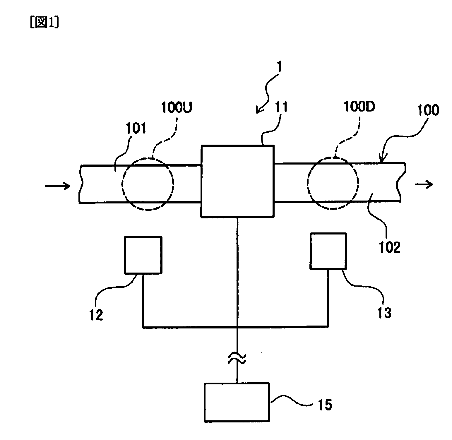
[0050]One embodiment of the present invention will now be described with reference to the accompanying drawings. As shown in FIG. 1, a flow sensor 1 in accordance with one embodiment of the present invention includes a heater (heating means) 11 attached to a part of a pipe 100 constituting a flow path to heat a part of the outer wall surface of pipe, infrared ray detecting sensors (non-contact temperature sensors) 12 and 13 for measuring the temperatures of outer wall surface portions of an upstream-side pipe 101 and a downstream-side pipe 102 of a portion heated by the heater 11 for the pipe 100 in a non-contact manner, respectively, and a control processing section 15 for controlling the heating value of the heater 11 and determining the flow rate of a fluid flowing in the pipe 100 from the temperature difference between the upstream-side infrared ray detecting sensor 12 and the downstream-side infrared ray detecting sensor 13 of the infrared ray detecting sensors 12 and 13.

[0051]...


PUM


Abstract

A flow meter includes a heating means (11) for heating a partial region of the outer wall surface of a pipe forming a flow path or for heating a particular region in the pipe; and temperature detecting means for measuring the temperatures of regions for radiating the temperature influence from the heated region to the outside as heat energy (infrared rays), the regions being on the upstream side and the downstream side of the pipe with respect to the heated region. The temperature detecting means consist of an upstream-side non-contact temperature detecting means (12) and a downstream-side non-contact temperature detecting means (13) arranged near the outer wall surface of the pipe in a state of being not in contact with the outer wall surface, and the non-contact temperature detecting means can measure the temperatures of the upstream-side heat energy radiating region and downstream-side heat energy radiating region in a state of being not in contact with the outer wall surface of the pipe. The flow rate of a fluid to be measured flowing in the flow path is measured from the temperature difference between the temperatures of the upstream-side heat energy radiating region and downstream-side heat energy radiating region measured by the non-contact temperature detecting means or from the output caused by the temperature difference.

Description

TECHNICAL FIELD[0001]The present invention relates to a flow sensor for measuring the flow rate of a fluid flowing in a flow path.BACKGROUND ART[0002]As a flow sensor for measuring the flow rate of a fluid, there is known a thermal flow sensor for sensing the flow rate of the fluid by detecting a change in electric power or a change in resistance caused by the absorption of heat of a heater by the fluid. For example, the outer periphery of a capillary having an outside diameter of about 0.5 mm is insultingly coated with a polyimide resin, and a wire of about several tens microns insultingly coated with a polyimide resin in the same way is wound on the coated capillary on the upstream side and the down stream side as a device that is part heater and part temperature sensor. By the flow of a gas in the capillary, in the device that is part heater and part temperature sensor on the upstream side, heat is absorbed by the gas flow, and the device on the downstream side is warmed by the h...

Claims


Application Information

Patent Timeline
IPC IPC(8): G01F1/68
CPCG01F1/6847G01F1/696G01F1/6884G01F1/68
Inventor KAMIUNTEN, SHOJINAKANO, SEISHI
Owner YAMATAKE HONEYWELL CO LTD
Why Eureka
Try Eureka