
Pump for Dispensing a Dose of a Fluid Product and Range Comprising Such Pumps

a technology for fluid products and pumps, which is applied in the direction of packaging, instruments, measurement devices, etc., can solve the problems of limited wear of pistons, and achieve the effect of limiting the modification of production machines and reducing the number of manufacturing operations

Active Publication Date: 2008-09-04
ALBEA LE TREPORT
View PDF11 Cites 19 Cited by
  • Summary
  • Abstract
  • Description
  • Claims
  • Application Information

AI Technical Summary

Benefits of technology

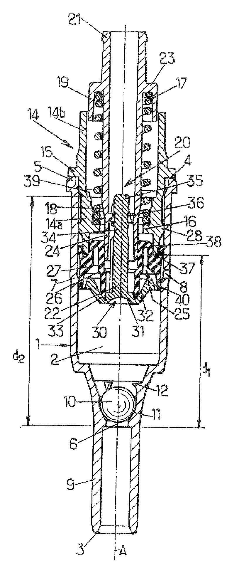
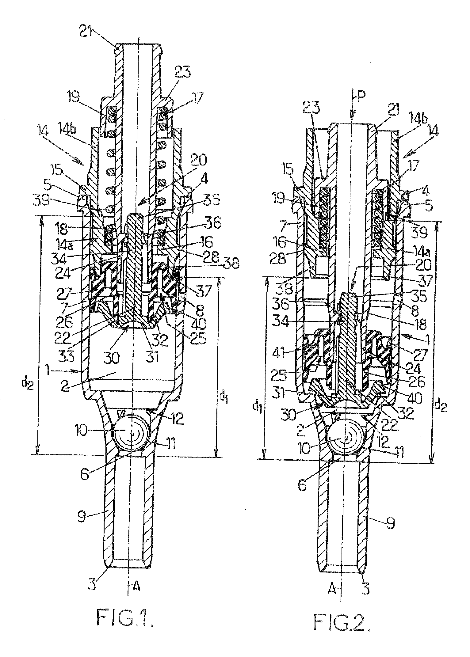
[0008]Thus, the collar guides the stem in the end member when the compression member is moved along the stroke. In addition, in the end-of-stroke position, the bearing of the collar on the shoulder is distributed uniformly within the end member. The compression member extends along the central axis at all steps in the operation of the pump, thereby ensuring that the piston bears in a distributed manner on the body. Sealing between the piston and the body may thus be provided and the wear of the piston may be limited.
[0013]The object of the invention is also to allow a range of pumps to be produced in a simple manner, in which the pumps, having similar components, materials, technical features and operation, can dispense doses of a fluid product of different volume.
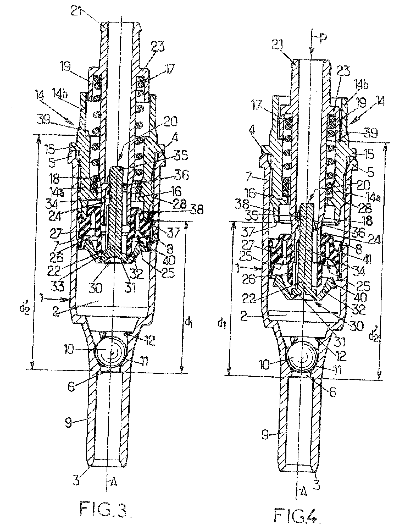
[0015]Each pump of such a range is adapted to dispense a dose of a fluid product having a defined volume. The end member forms a single module making it possible for the volume of the dose to be dispensed to be adjusted in such a way as to reduce the number of manufacturing operations and to limit the modification of the production machines which is needed to vary the volumes of the dose to be dispensed by the pumps of one and the same range.

Problems solved by technology

Sealing between the piston and the body may thus be provided and the wear of the piston may be limited.

Method used


Image

  • Pump for Dispensing a Dose of a Fluid Product and Range Comprising Such Pumps
  • Pump for Dispensing a Dose of a Fluid Product and Range Comprising Such Pumps
  • Pump for Dispensing a Dose of a Fluid Product and Range Comprising Such Pumps

Examples


Embodiment Construction

[0021]In the figures, the same references denote identical or similar elements.

[0022]The figures show one particular embodiment of a pump for dispensing a dose of a liquid or viscous fluid product, for example in the field of perfumery, pharmacy, cosmetics or the like.

[0023]The pump may belong to a range of pumps, in which range pumps having similar components, materials, technical features and operation are designed to dispense doses of a fluid product having different volumes.

[0024]The pump comprises:[0025]a tubular body 1 extending along a central axis A between a first end 3 and a second end 4 and having an intake orifice 6 for the fluid product near the first end 3; and[0026]a compression member mounted so as to move inside the body 1 along an axial stroke between a rest position, away from the intake orifice 6 (FIGS. 1 and 3), and an end-of-stroke position, near the intake orifice 6 (FIGS. 2 and 4), the compression member having an exhaust orifice.

[0027]The pump is intended to...


PUM


Abstract

Pump for dispensing a dose of a fluid product, comprising a tubular body including an intake orifice; an end member associated with the body and including a rest abutment and an end-of-stroke abutment; a compression member mounted so as to move inside the body between a rest position in which said compression member is in abutment against the rest abutment, and an end-of-stroke position in which said compression member is in abutment against the end-of-stroke abutment, said compression member being elastically returned toward the rest position and including an exhaust orifice; a metering chamber; and an intake valve and an exhaust valve adapted to selectively close off the intake orifice and the exhaust orifice, respectively.

Description

CROSS-REFERENCE TO RELATED APPLICATIONS[0001]The present application claims priority of French patent application No. 07 00462 filed on Jan. 23, 2007, the content of which is incorporated herein by reference.FIELD OF THE INVENTION[0002]The invention relates to a pump for dispensing a dose of a fluid product and also to a range comprising such pumps.BACKGROUND OF THE INVENTION[0003]More particularly the invention relates to a pump for dispensing a dose of a fluid product, comprising: a tubular body extending along a central axis between a first end and a second end and including an intake orifice near the first end; an end member having a central opening and associated with the second end of the body, the end member having a tubular wall that extends along the central axis and has an outer surface and an inner surface, the end member including a rest abutment and an end-of-stroke abutment; compression member mounted so as to move inside the body along an axial stroke between a rest p...

Claims


Application Information

Patent Timeline
IPC IPC(8): G01F11/00
CPCB05B11/3007B05B11/3074B05B11/3025B05B11/3008B05B11/1007B05B11/1008B05B11/1025B05B11/1023B05B11/1074
Inventor LANGLOIS, YOHANNROY, CHRISTOPHE
Owner ALBEA LE TREPORT
Learn More