
Electric power converter

a technology of electric power converter and converter, applied in the direction of power conversion system, dc-dc conversion, climate sustainability, etc., can solve the problems of only increasing current and failing to efficiently increase frequency, and achieve the effect of efficient conversion of voltag

Inactive Publication Date: 2008-09-04
HONDA MOTOR CO LTD
View PDF5 Cites 17 Cited by
  • Summary
  • Abstract
  • Description
  • Claims
  • Application Information

AI Technical Summary

Benefits of technology

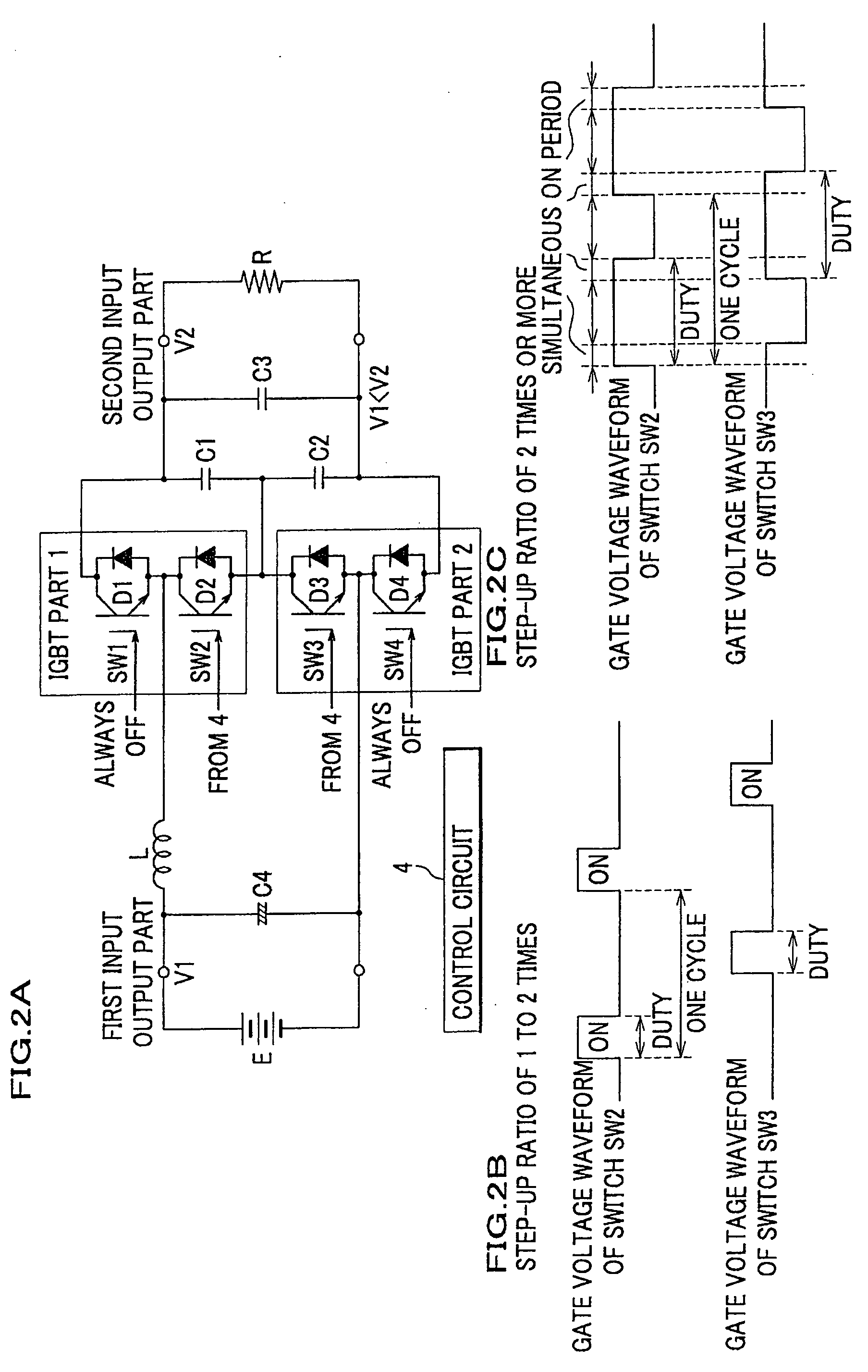
The present invention provides an electric power converter that can efficiently step up or down in DC / DC converter mode. The converter is small and lightweight, and can perform a continuous step-down operation without interrupting the output current. It also allows for a high step-up ratio of two times or more even if the number of capacitors is two. The converter includes a control circuit that makes ON / OFF control of the plurality of switches and selectively charges the inductor and capacitors. The control circuit also controls the simultaneous turning on of multiple switches to set up a period of simultaneous current flow. This results in a large amount of current passing through the inductor and magnetic energy accumulation, which can be used to generate a voltage with a step-up ratio of two times or more. The converter can be used in a variety of modes, such as step-up, step-down, regeneration, and continuity. It also allows for noise reduction and efficient step-down operation even at a low step-down ratio.

Problems solved by technology

Moreover, merely simultaneously turning the plurality of switches only increases a current and fails to efficiently increase its frequency.

Method used


Image

  • Electric power converter
  • Electric power converter
  • Electric power converter

Examples


Embodiment Construction

[0055]Next, the best mode to carry out the present invention will be explained with reference to drawings.

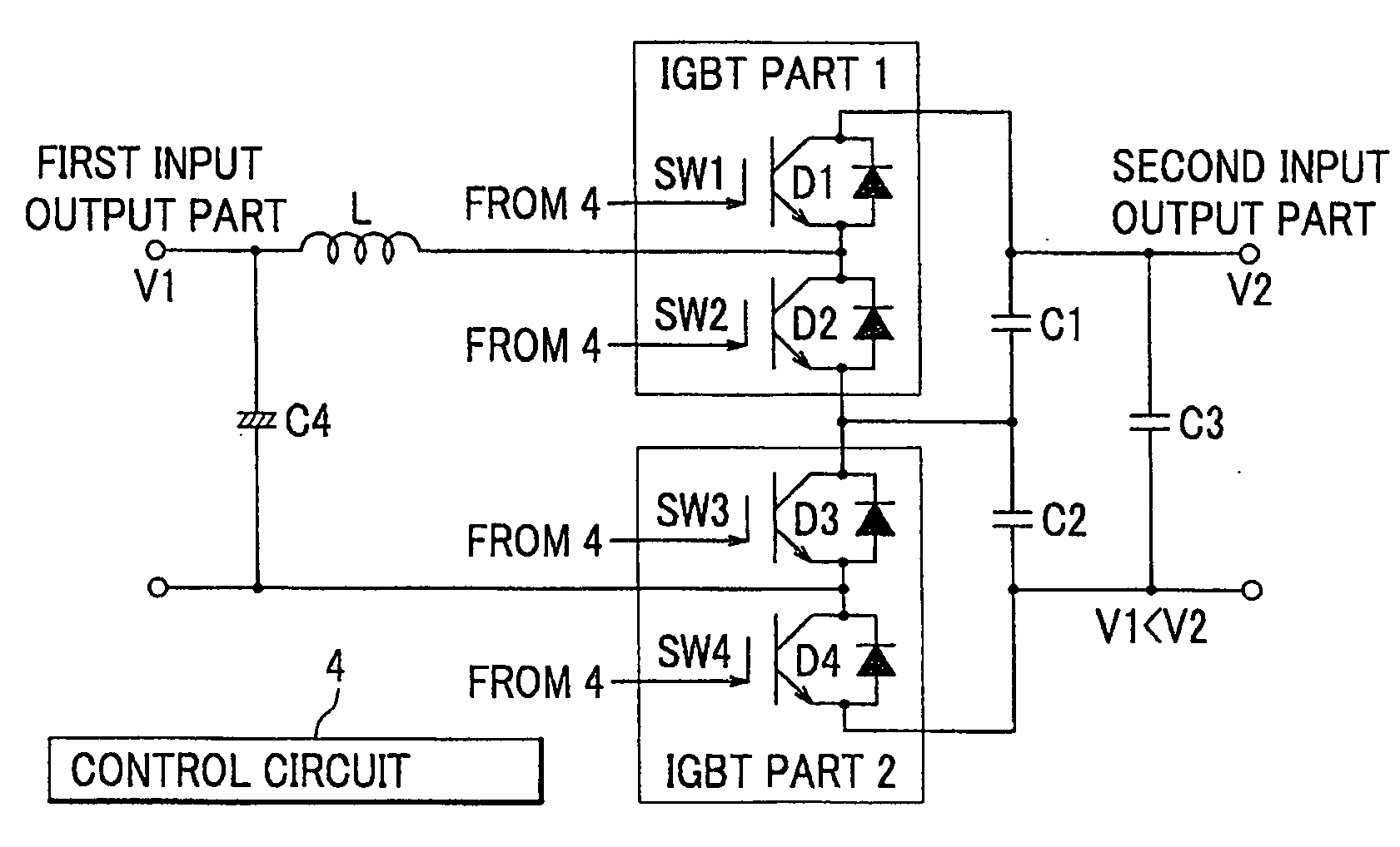
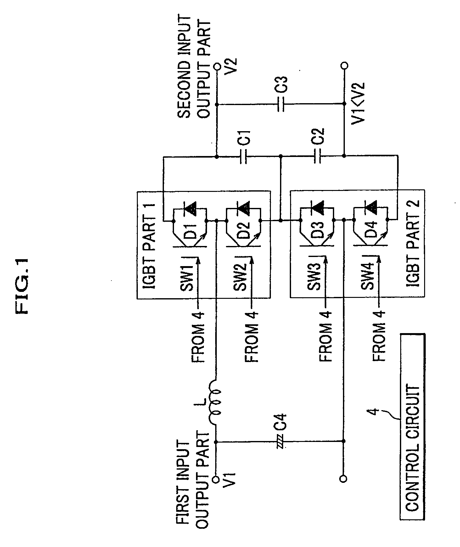
[0056]FIG. 1 shows a circuit diagram for a DC / DC converter which is a step-up and step-down electric power converter in a first preferred embodiment of the present invention. The DC / DC converter of the preferred embodiment includes step-up mode (for example, a power supply voltage of a DC power input part can be stepped up one to two times or more), electrical continuity mode, regenerative mode (a step-up operation can be made with a step-up ratio of zero to one times).

[0057]The difference between the DC / DC converter in the preferred embodiment shown in FIG. 1 and the DC / DC converter disclosed in Patent Document 4 JP 2005-22406A described above by referring to FIG. 14 and FIG. 15 as a conventional example lies in a method for ON / OFF control of a plurality of switches. That is, except for the control circuit part 4 which controls turning ON / OFF a plurality of switches, a circuit ...


PUM


Abstract

The invention provides an optimal electric power converter for a DC / DC converter which variably steps up a voltage successively with an optional magnification of one to two times or more and / or step down a voltage successively with a step-down ratio of one time or less. The converter includes a first input-output part, an inductor connected with a positive or a negative electrode side of the first input-output part, plural switches, plural capacitors, a second input-output part connected with plural capacitors, and a control circuit, wherein the control circuit controls the plural switches with operation mode and makes the inductor and plural capacitors selectively functional, wherein the electric power converter is of a switched capacitance type that performs any operation out of step-up, step-down, regeneration, and continuity, and wherein the control circuit controls to have a period for which two switches out of the plural switches are simultaneously turned ON.

Description

BACKGROUND OF INFORMATION[0001]1. Field of the Invention[0002]The present invention relates to an electric power converter suitable for a DC / DC converter, particularly, which steps up a direct voltage at an optional magnification of one to two times or more and steps down the direct voltage at an optional magnification of one time or less.[0003]2. Description of the Related Art[0004]An electric power converter includes a DC / DC converter which converts DC (direct current) voltage. The DC / DC converter is used in various devices, for example, a power generator using a solar cell, a wind power generator, a fuel cell system, a hybrid vehicle and the like. In particular, if the DC / DC converter is applied in a technological domain, wherein there is severe, spatial and weight limitations, particularly in a motor vehicle, more demands for downsizing and weight reduction of the DC / DC converter are generated.[0005]As for a conventional step-up DC / DC converter, for example, in a step-up DC / DC c...

Claims


Application Information

Patent Timeline
Patent Type & Authority Applications(United States)
IPC IPC(8): H02M3/07
CPCH02M3/158Y02B70/1466H02M3/1588Y02B70/10
Inventor WATANABE, YASUTOHIRAKAWA, MITSUAKIHASHINO, SATOSHI
Owner HONDA MOTOR CO LTD
Learn More