Camera Modules With Lens Drive Device

a technology of lens drive device and camera module, which is applied in the field of camera, can solve the problem of general decrease of the space available for camera module in the cell phon

Inactive Publication Date: 2008-09-04
NANOMOTION
View PDF16 Cites 26 Cited by
  • Summary
  • Abstract
  • Description
  • Claims
  • Application Information

AI Technical Summary

Benefits of technology

[0019]Optionally, the zoom platform is selectively “dockable” in a telephoto position along the optic axis of the camera module or a wide-angle position along the axis to provide a telephoto or wide-angle image of a scene. As in the case of a turret-drive system noted above, docking of the zoom lens is optionally accomplished by at least one flexible latch and a corresponding at least one catch. In either the wide-angle or telephoto positions of the zoom platform, the AF platform may be positioned along the camera module optic axis by operation of its at least one piezoelectric motor to provide appropriate focusing of the image on the module photosurface.

Problems solved by technology

Furthermore, whereas there is demand that cell phone camera modules provide image quality and functions that keep pace with improving image quality and an increasing number of functions offered by conventional digital cameras, space available for camera modules in cell phones is generally decreasing as cell phones become thinner and smaller.

Method used


Image

  • Camera Modules With Lens Drive Device
  • Camera Modules With Lens Drive Device
  • Camera Modules With Lens Drive Device

Examples


Embodiment Construction

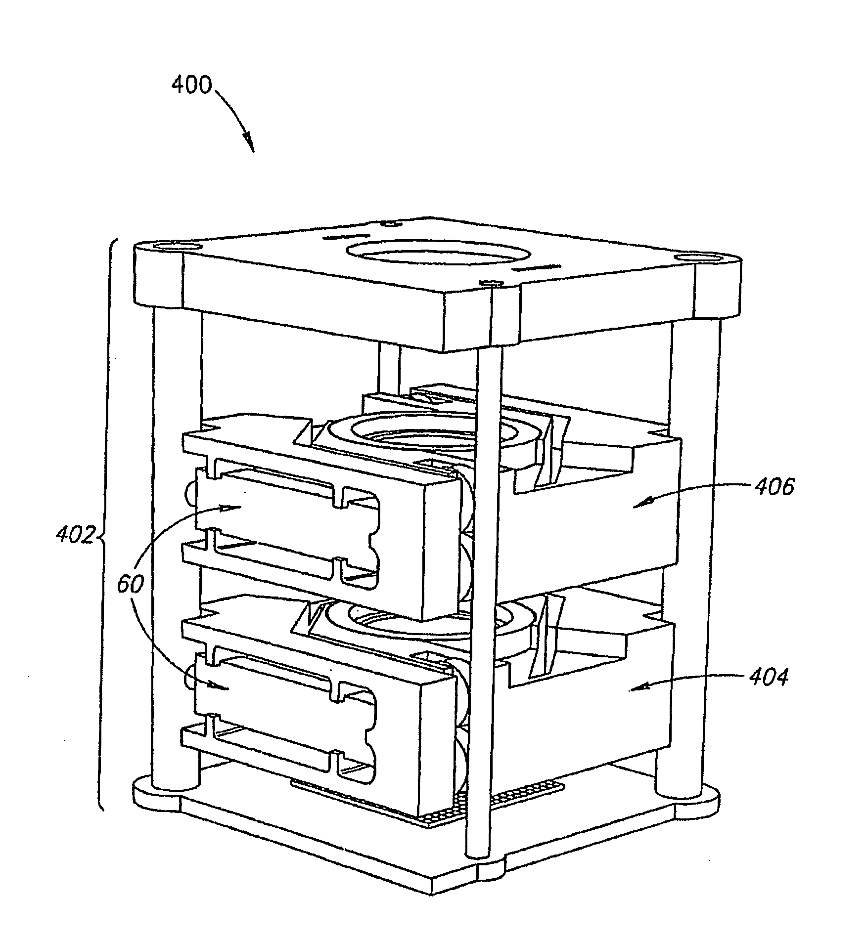
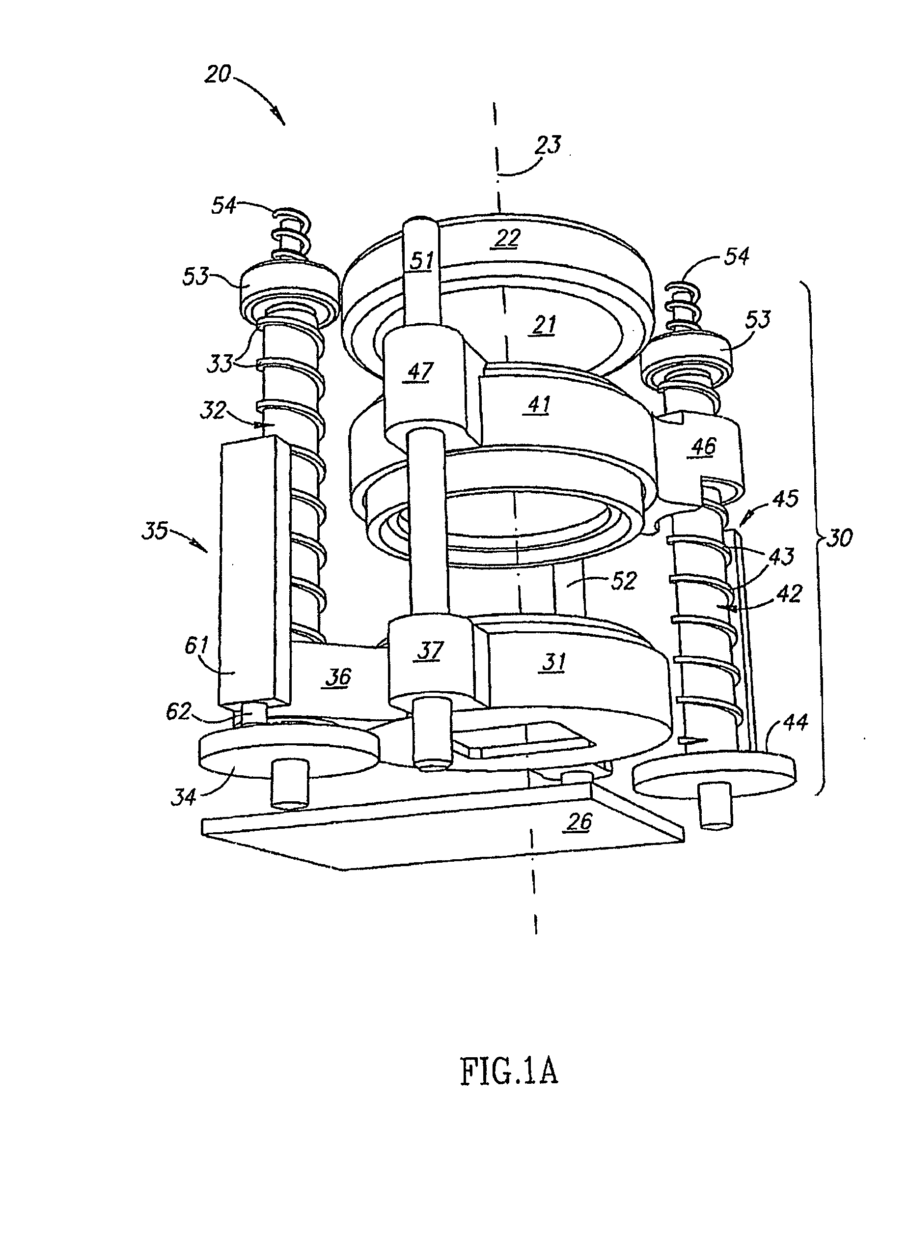
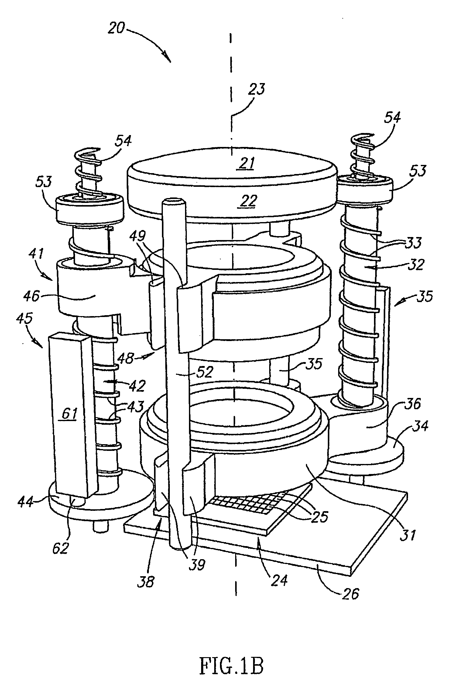
[0076]FIGS. 1A and 1B schematically show different perspective views of components of a camera module 20, in accordance with an embodiment of the present invention.

[0077]Camera module 20 optionally comprises a worm-drive system 30 comprising AF and zoom platforms 31 and 41 for positioning AF and zoom lenses or lens systems (not shown in FIGS. 1A and 1B) in the camera module that are respectively mounted to the AF and zoom platforms. A collecting lens 21 is optionally mounted to a collecting lens frame 22 and has an optic axis coincident with an optic axis, represented by a dashed line 23, of camera module20. Collecting lens 21 receives light from a scene being imaged by camera module 20 and transmits the collected light to zoom and AF lenses mounted to AF and zoom platforms 31 and 41. Worm drive system 30 positions the AF and zoom lens platforms 31 and 41 and thereby their respective AF and zoom lenses to selectively focus the received light in a wide-angle or telephoto image of the...


PUM


Abstract

A camera module has a plurality of lenses aligned along an optic axis that receive and transmit light from a scene being imaged by the camera module. At least one lens is mounted on a platform which is movable along the optic axis and is moved by action of a piezoelectric motor. Optionally, at least one lens is mounted on a second platform which is movable along the optic axis. The second platform may be driven by a second piezoelectric motor or moved by action of the first platform.

Description

RELATED APPLICATIONS[0001]This application claims the benefit under 35 U.S.C. 119(a) of Japanese Patent Application No. P2004-283060 filed on Sep. 29, 2004, Japanese Patent Application No. P2004-283061 filed on Sep. 29, 2004, and Japanese Patent Application No. P2004-283193 filed on Sep. 29, 2004 the disclosures of which are incorporated herein by reference.FIELD OF THE INVENTION[0002]The invention relates to cameras and in particular camera modules suitable for integration into portable communication devices, such as cell phones, and the portable communication devices comprising such camera modules.BACKGROUND OF THE INVENTION[0003]Camera modules embedded in cell phones offer many of the same features offered by conventional digital cameras and comprise many of the same components as conventional digital cameras. Cell phone camera modules generally provide an auto focus (AF) function and a zoom function and comprise a photosensitive surface such as a CCD or CMOS photosurface on whic...

Claims


Application Information

Patent Timeline
Patent Type & Authority Applications(United States)
IPC IPC(8): H04N5/225G02B7/02
CPCG02B7/102H04N5/2254G02B13/009H04N23/55G03B13/36G03B3/10G03B30/00G03B5/04G03B2205/0061G03B2205/0023H04N23/57
Inventor AVITAL, ALONELHAYANI, HOVAVPELED, GALKARASIKOV, NIRGANOR, ZE'EV
Owner NANOMOTION
Why Eureka
Try Eureka