Spray Nozzle

Inactive Publication Date: 2008-09-11
DELAVAN
View PDF5 Cites 19 Cited by
  • Summary
  • Abstract
  • Description
  • Claims
  • Application Information

AI Technical Summary

Benefits of technology

[0017]Preferably the central bore of the nozzle body further includes a second interior locating surface having two radially opposed recesses formed therein. The second interior surface is positioned radially outward of the interior locating surface so as to facilitate the communication of fluid between the upstream portion of the swirl element peripheral surface and the nozzle body.
[0018]In a preferred embodiment, the spray nozzle of the present disclosure further includes a locking plate disposed within the central bore of the nozzle body and positioned upstream of the swirl element. The locking plate is rotatably engaged within radially opposed recesses formed in the central bore of the nozzle body. It is envisioned that the recesses are formed in a plane which passes through the central axis of the nozzle at a right angle. In an alternate embodiment, the recesses are angled with respect to a plane passing through and perpendicular to the central axis. As a result, the rotational engagement of the locking plate with the recesses increases a contact pressure applied by the locking plate to the swirl element. It is presently preferred that the locking plate also

Problems solved by technology

However, difficulty is often encountered when attempting to engage the nozzle body, including the orifice disc and associated O-ring, with the adapter.

Method used


Image

  • Spray Nozzle
  • Spray Nozzle
  • Spray Nozzle

Examples


Embodiment Construction

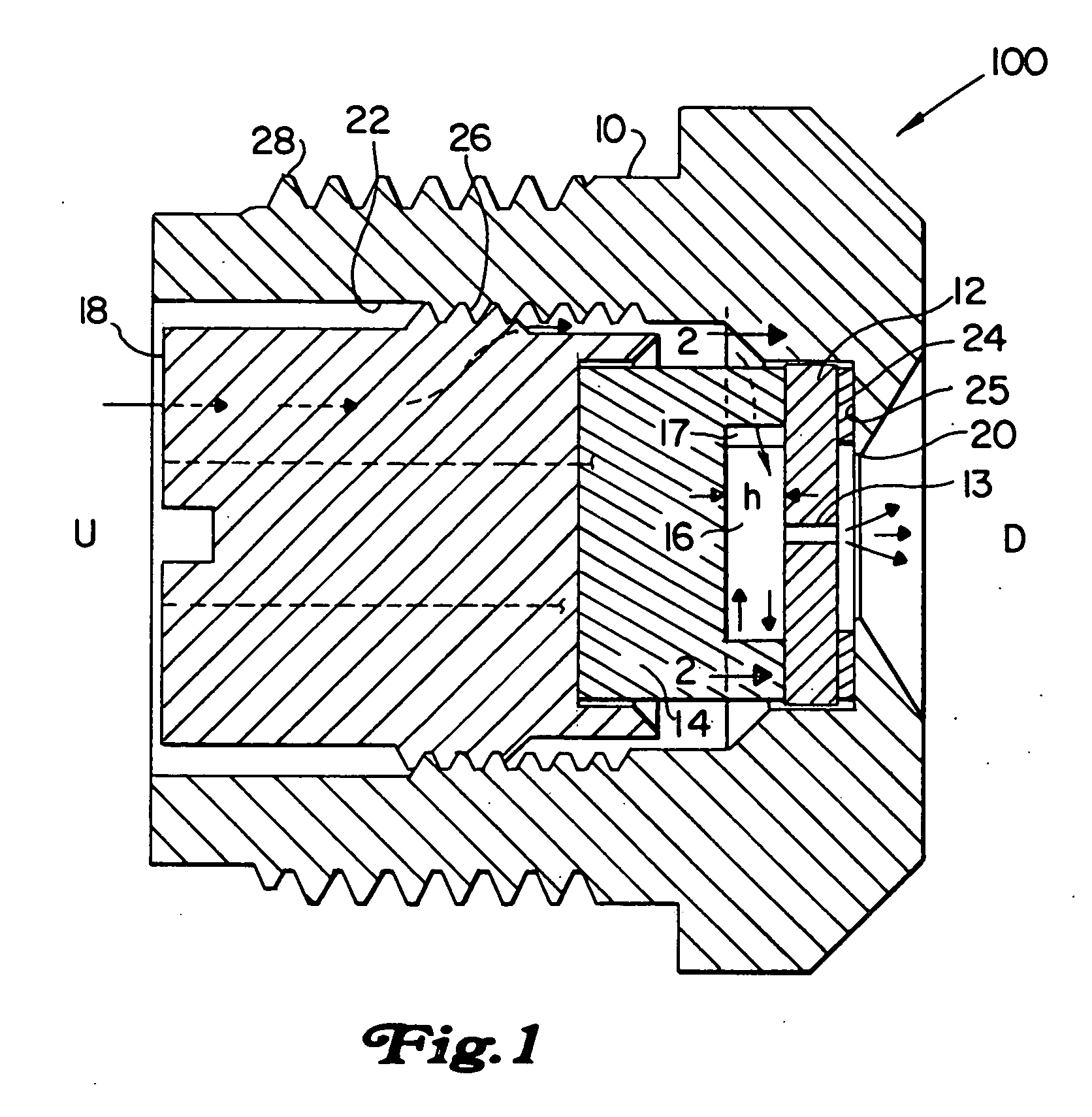
[0038]In the description which follows, as is common in the art to which the subject invention appertains, “upstream side” shall refer to the end of the component which faces the inlet side of the nozzle, while “downstream side” shall refer to the side that faces the discharge orifice of the nozzle. In FIGS. 1, 2 and 6a the upstream and downstream ends of the nozzle are identified by reference characters U and D respectively.

[0039]Referring now to the drawings wherein like reference numerals identify similar elements of the subject invention, there is illustrated in FIG. 1 a prior art spray nozzle designated generally by reference numeral 100. As shown herein, spray nozzle 100, includes a nozzle body 10, an orifice disc 12, a swirl chamber block member 14, and a retainer member 18 for retaining and positioning the orifice disc 12 and chamber member 14 in the nozzle body 10.

[0040]The nozzle body 10 is constructed from stainless steel and includes an opening 20 at the downstream end f...


PUM


Abstract

A spray nozzle (300) which employs a locking and an alignment feature (330) to facilitate the replacement of internal nozzle components. The spray nozzle includes a nozzle body (310), a swirl element (314) and an orifice disc (312). The nozzle body defines a central bore which extends between a fluid receiving section and a fluid discharge section and delineates a central axis and delimits an interior locating surface for swirl element and the orifice disc. The orifice disc includes a protuberance (374) associated with the downstream surface thereof which protrudes into the spray opening of the nozzle body.

Description

BACKGROUND OF THE INVENTION[0001]1. Field of the Invention[0002]The subject invention relates to spray nozzles for use in spray drying applications, and more particularly to, spray nozzles of the type which employ locating and / or wear part retention / locking features to facilitate ease of replacement and handling of internal nozzle components and the reinstallation of the assembled unit in the nozzle location.[0003]2. Background of the Related Art[0004]Fluid nozzles or atomizers having a spiral swirl chamber and a spray orifice disposed within a nozzle body have been employed in the past for various applications, including spray drying, aeration, cooling, and fuel injection. U.S. Pat. No. 3,680,793 to Tate, which is herein incorporated by reference in its entirety, discloses a spray nozzle that includes a swirl chamber configured such that the origin of the spiral flow in the swirl chamber and the spray orifice formed in the orifice disc are eccentrically offset relative to each othe...

Claims


Application Information

Patent Timeline
IPC IPC(8): B05B1/34B05B15/06B05B1/00B05B15/65
CPCB05B1/00B05B15/065B05B1/3436B05B15/65B05B1/3415
Inventor WHITTAKERLLOYD, JAMES E.PERCIVAL, DAVID R.
Owner DELAVAN
Why Eureka
Try Eureka