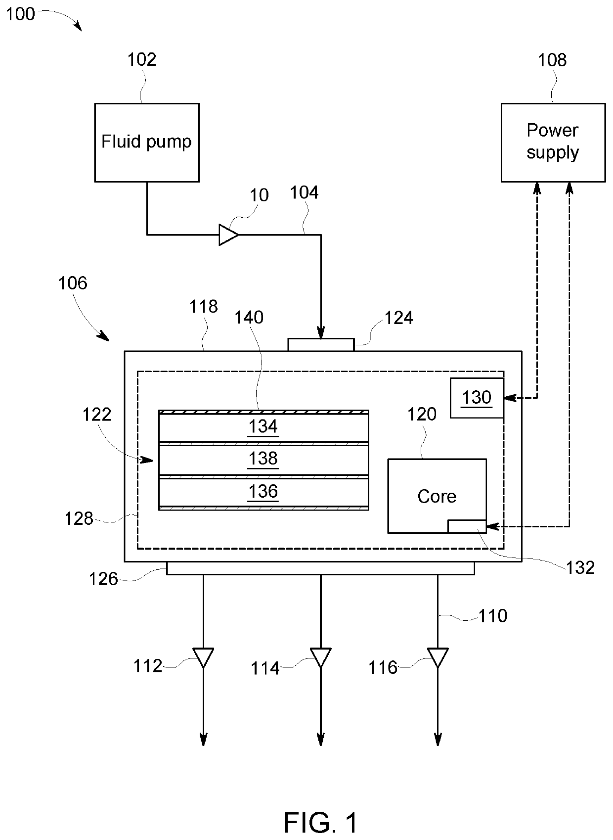
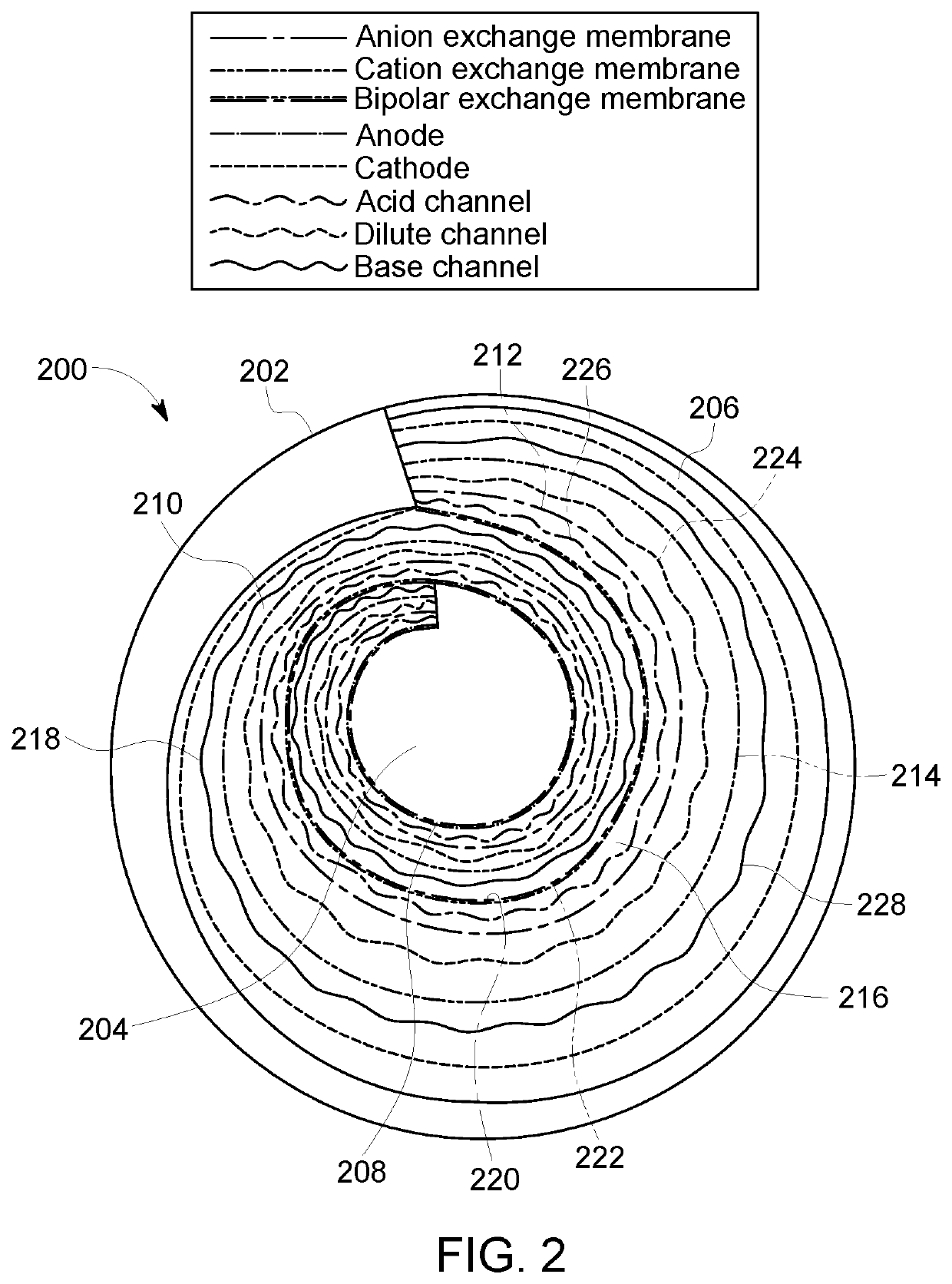
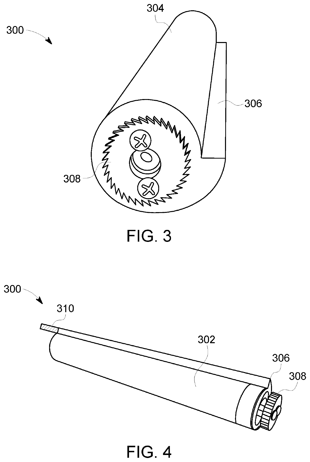
Spiral wound bipolar electrodialysis cell

a bipolar electrodialysis and spiral wound technology, applied in membrane technology, membrane separation processes, membranes, etc., can solve the problems of significant increase in the cost of the electrodialysis cell, damage to the stack of membranes, and inability to meet the needs of deep sea and/or other high pressure environments, so as to facilitate fluid communication

Pending Publication Date: 2020-03-05
VETCO GRAY SCANDINAVIA
View PDF4 Cites 0 Cited by
  • Summary
  • Abstract
  • Description
  • Claims
  • Application Information

AI Technical Summary

Benefits of technology

[0006]In yet another aspect, a method for assembling an electrodialysis cell is provided. The method includes coupling a membrane assembly to a core including a first electrode, winding the membrane assembly around the core in a spiral wound configuration, inserting the wound membrane assembly and the core into an internal chamber of a housing, positioning, within the internal chamber, a second electrode between the housing and the membrane assembly, and sealing the membrane assembly within the internal chamber. The membrane assembly includes a plurality of ion exchange membranes spaced from each other to define a plurality of fluid channels. The housing includes an inlet end and an outlet end. The fluid channels facilitate fluid communication between the inlet and outlet ends. The membrane assembly is positioned between the first and second electrodes. The inlet end includes an inlet nozzle to transfer a feed fluid to the plurality of fluid channels and the outlet end includes a set of outlet nozzles to transfer at least one output fluid from the plurality of fluid channels.

Problems solved by technology

However, at least some known electrodialysis cells in the stack configuration (also known as a “plate and frame” configuration) are not suitable for deep sea and / or other high pressure environments.
Additionally, the ambient pressure of the environment may damage the stack of membranes.
Although a pressure vessel may be built for the plate and frame configuration, the pressure vessel must be occupied by a high pressure inert gas to balance the ambient pressure, which may significantly increase costs of the electrodialysis cell.

Method used


Image

  • Spiral wound bipolar electrodialysis cell
  • Spiral wound bipolar electrodialysis cell
  • Spiral wound bipolar electrodialysis cell

Examples


Embodiment Construction

[0023]In the following specification and the claims, reference will be made to a number of terms, which shall be defined to have the following meanings.

[0024]The singular forms “a”, “an”, and “the” include plural references unless the context clearly dictates otherwise.

[0025]“Optional” or “optionally” means that the subsequently described event or circumstance may or may not occur, and that the description includes instances where the event occurs and instances where it does not.

[0026]Approximating language, as used herein throughout the specification and claims, may be applied to modify any quantitative representation that may permissibly vary without resulting in a change in the basic function to which it is related. Accordingly, a value modified by a term or terms, such as “about”, “approximately”, and “substantially”, are not to be limited to the precise value specified. In at least some instances, the approximating language may correspond to the precision of an instrument for m...


PUM

PropertyMeasurementUnit
electric currentaaaaaaaaaa
currentaaaaaaaaaa
electric potentialaaaaaaaaaa

Abstract

An electrodialysis cell includes a housing defining an internal chamber, a core positioned within the internal chamber, a first electrode positioned in the internal chamber adjacent the housing, a second electrode coupled to the core and spaced from the first electrode, and a membrane assembly positioned between the first and second electrodes in a spiral wound configuration. The housing includes an inlet end for receiving a feed fluid and an outlet end in fluid communication with the inlet end. The membrane assembly includes a plurality of ion exchange membranes spaced from each other to define a plurality of fluid channels between the inlet and outlet ends.

Description

BACKGROUND[0001]The field of the disclosure relates generally to electrodialysis cells, and more specifically, to spiral-wound, bipolar electrodialysis cells.[0002]Electrodialysis cells use electric potential to separate a feed fluid into several output streams. In particular, electrodialysis cells include a stack of flat ion exchange membranes that are arranged in a spaced apart configuration to define a set of fluid channels. The membranes are positioned between two electrodes. When current is applied to the electrodes, ions from the feed fluid travel towards each electrode. The membranes selectively pass either negatively charged or positively charged ions while inhibiting ions of the opposite charge from passing through. The selective passing of ions through the membranes creates a plurality of output streams having different concentrations of acids, bases, and / or salts. In one example, electrodialysis cells are used for desalination of seawater (e.g., for generating potable wat...

Claims


Application Information

Patent Timeline
Patent Type & Authority Applications(United States)
IPC IPC(8): B01D61/44B01D63/10B01D69/06C02F1/469
CPCB01D69/06C02F2103/08B01D61/445B01D63/10C02F1/4693B01D2325/42C02F1/469
Inventor XIA, ZIJUNZHANG, CHENGQIANRONG, WUJUNZHENG, YONGCHANGBATCHELDER, BRUCEBARBER, JOHN H.CAO, LEIWANG, HUASTACHERA, DAVID MICHAELYAN, BO
Owner VETCO GRAY SCANDINAVIA
Why Eureka
Try Eureka