Hybrid transmission coolant flow management system

A technology for transmission devices and electric motors, applied in transmission devices, fluid transmission devices, belts/chains/gears, etc., can solve problems such as torque converter rotation loss

Pending Publication Date: 2019-02-26
FORD GLOBAL TECH LLC
View PDF0 Cites 0 Cited by
  • Summary
  • Abstract
  • Description
  • Claims
  • Application Information

AI Technical Summary

Problems solved by technology

Such oil accumulation may cau

Method used


Image

  • Hybrid transmission coolant flow management system
  • Hybrid transmission coolant flow management system
  • Hybrid transmission coolant flow management system

Examples


Embodiment Construction

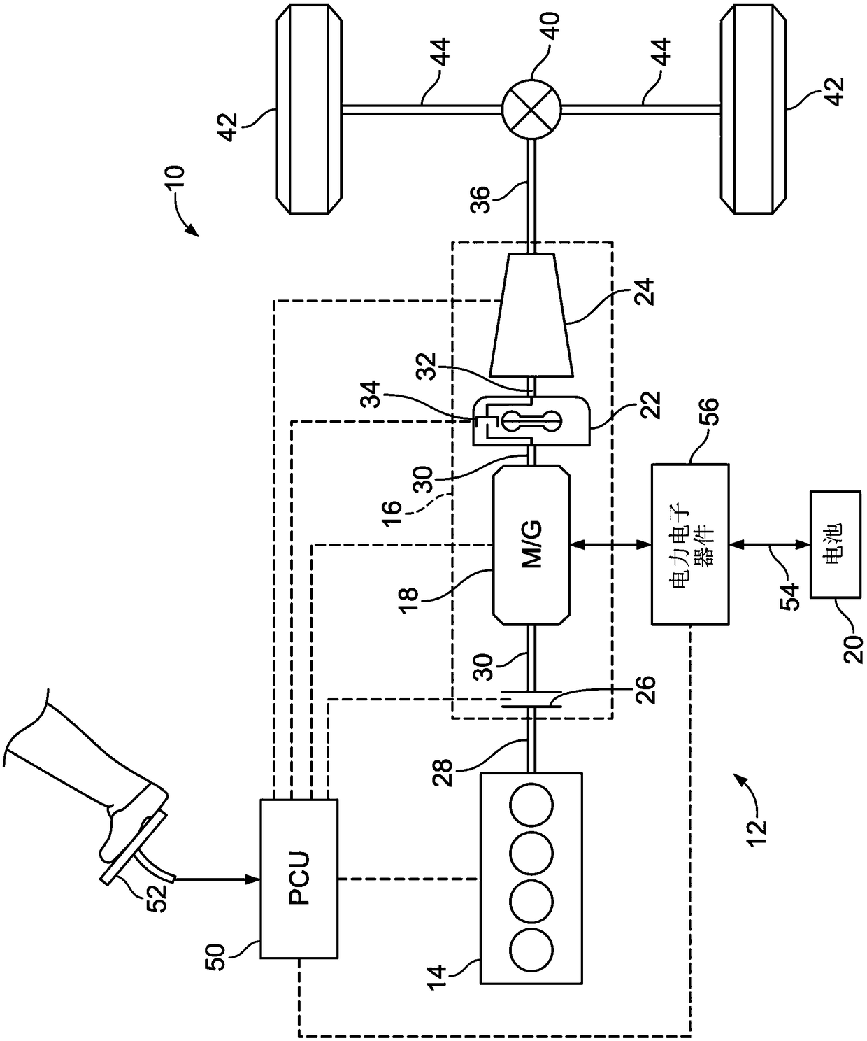
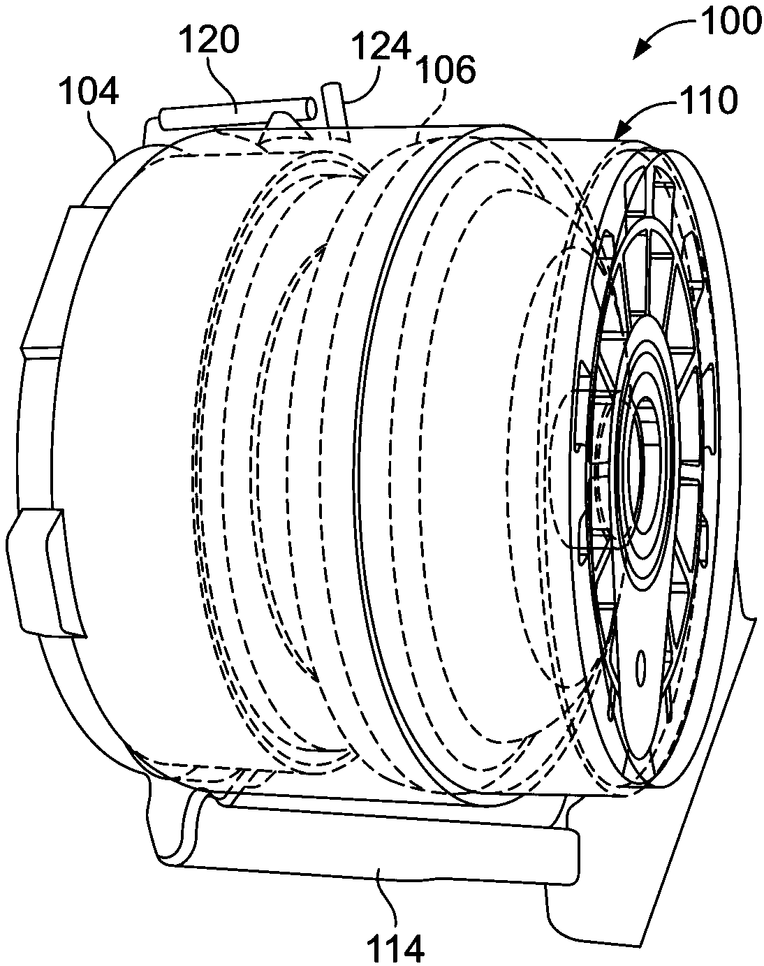
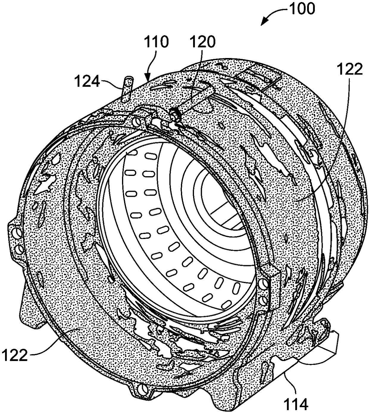
[0017] The embodiments of the present disclosure are described here. However, it should be understood that the disclosed embodiments are only examples, and other embodiments may take various alternative forms. The drawings need not be drawn to scale; some features may be exaggerated or minimized to show details of specific components. Therefore, the specific structural and functional details disclosed herein should not be construed as limiting, but only as a representative basis for teaching those skilled in the art to utilize the embodiments in various forms. As those of ordinary skill in the art will understand, the various features shown and described with reference to any one of the drawings can be combined with features shown in one or more other drawings to produce features that are not explicitly shown or described. 的实施例。 Example. The combinations of features shown provide representative embodiments for typical applications. However, various combinations and modificati...


PUM


Abstract

The invention relates to a hybrid transmission coolant flow management system. A transmission assembly including a housing, an electric motor, and a baffle is provided. The housing may include first and second drainage channels. The electric motor may be disposed within the housing adjacent the drainage channels and a torque converter. The baffle may be disposed within the housing upon a housing inner surface, and may define an opening to the first and second drainage channels. The baffle may include a baffle flange sized for positioning adjacent the torque converter to minimize contact of oilwithin the housing to the torque converter. The housing may define first and second partition walls each partially extending over one of the first and second drainage channels. The baffle may furtherinclude first and second seal features each disposed at one of two baffle ends.

Description

Technical field [0001] The present disclosure relates to a coolant flow management system for a hybrid power transmission device of a vehicle. Background technique [0002] Vehicle torque converters usually operate in a dry environment. The torque converter of a hybrid power transmission device usually operates in a wet environment. Packaging constraints between the torque converter and the transmission may limit cooling oil emissions. For example, oil may accumulate around electric motors and torque converters. Such oil accumulation may cause rotational loss of the torque converter. Summary of the invention [0003] A transmission device assembly includes a housing, an electric motor and a baffle. The housing includes a first discharge channel and a second discharge channel. The electric motor is disposed in the housing adjacent to the first discharge passage, the second discharge passage, and the torque converter. The baffle is disposed on the inner surface of the housing ...

Claims


Application Information

Patent Timeline
IPC IPC(8): F16H41/30
Inventor 张登富马克·斯图尔德威廉·瑞雷布赖恩·理查德·莱特
Owner FORD GLOBAL TECH LLC
Why Eureka
Try Eureka