

Bumper beam for automobile
- Summary
- Abstract
- Description
- Claims
- Application Information
AI Technical Summary
Benefits of technology
Problems solved by technology
Method used
Image

Examples
first embodiment
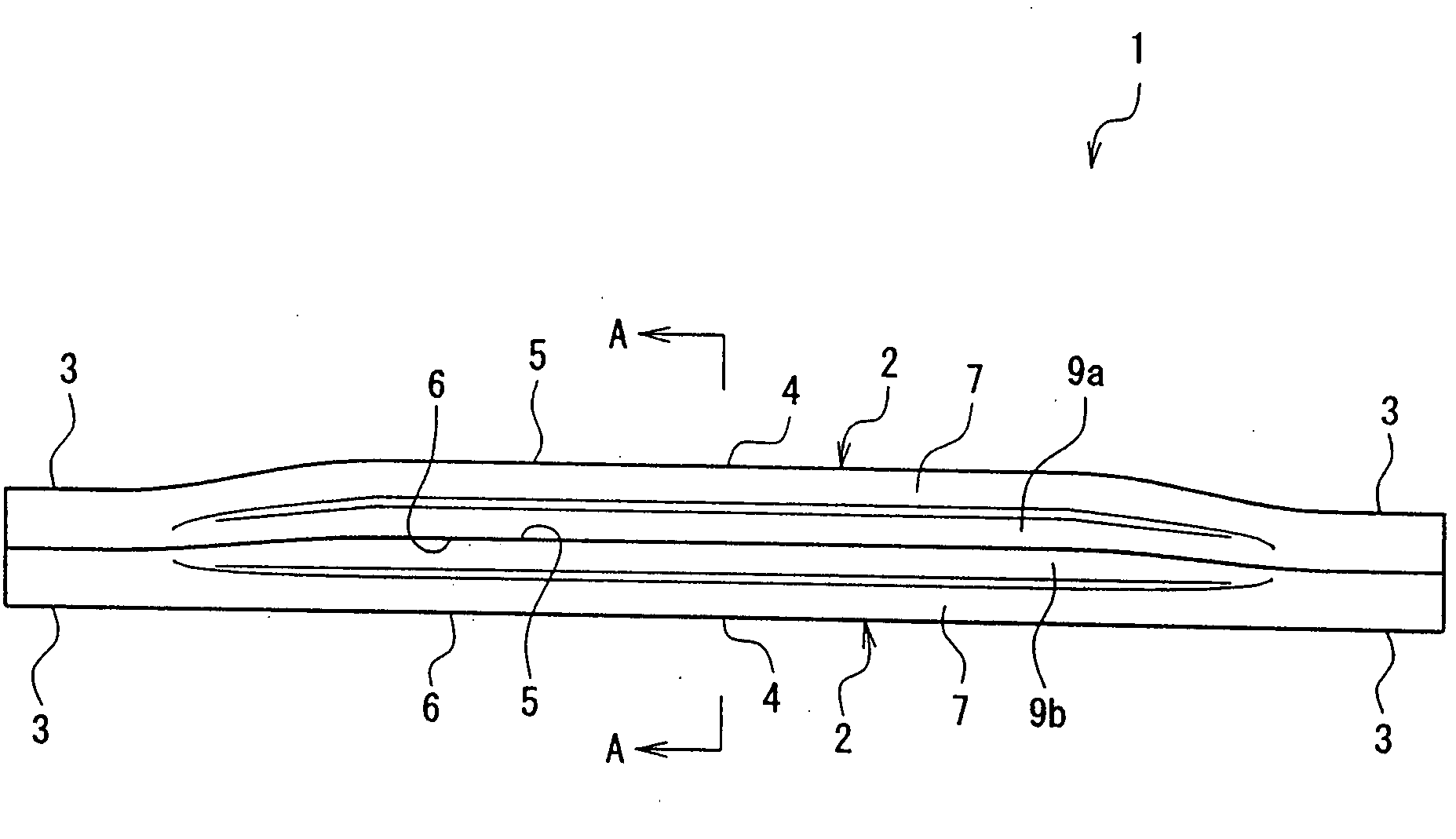
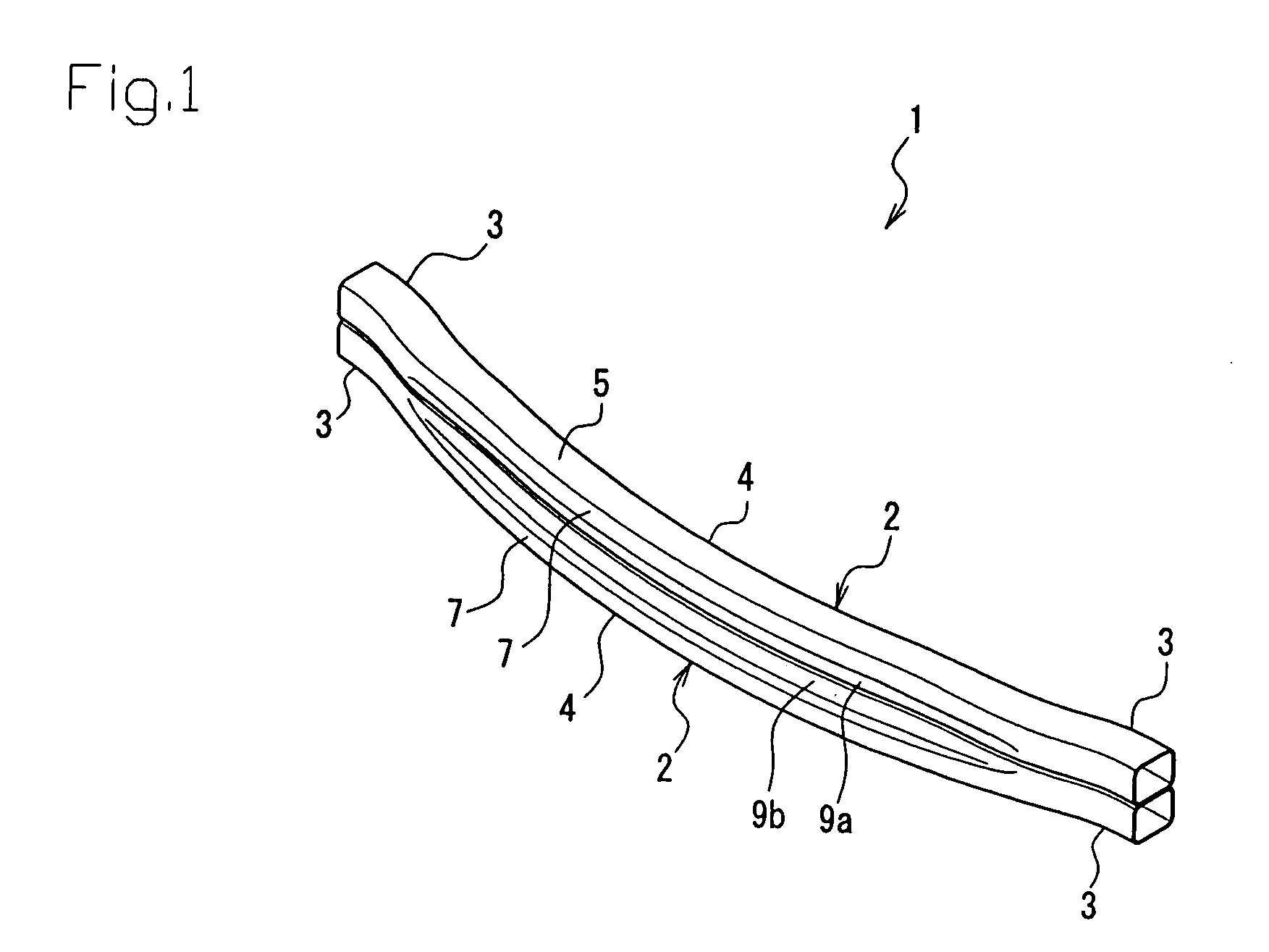
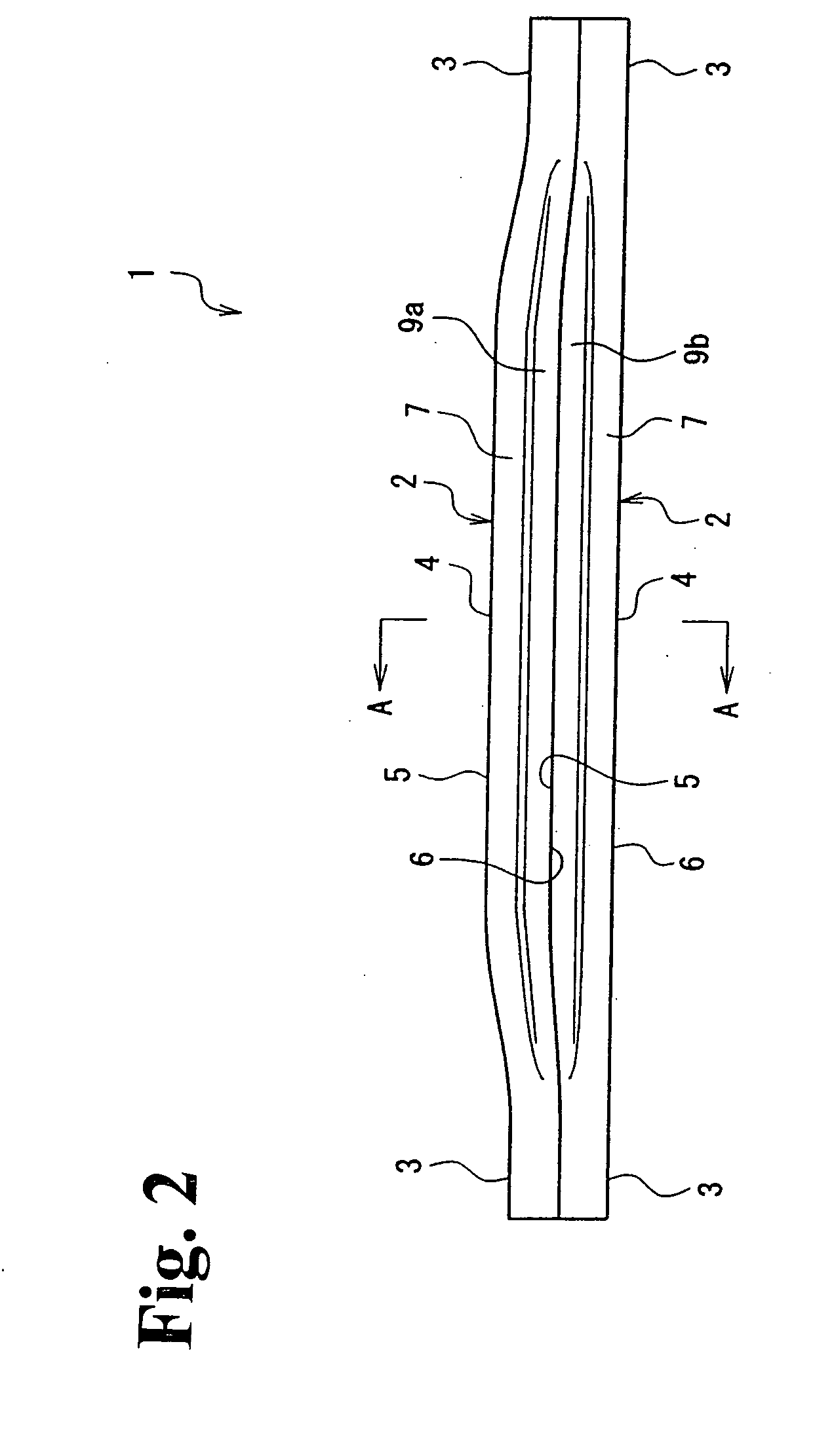
[0080]FIGS. 1-3 show the present invention. The legend 1 in the drawings is a bumper beam for automobile that protects an automobile from impact in a collision. This bumper beam 1 is a constituent body disposed on the inner side of a bumper face, and extends longitudinally left and right and is attached to the front or rear of an automobile.
[0081]This bumper beam 1 comprises a plurality of tubular bodies 2, 2 formed by tube hydroforming and extending left and right. The plurality of tubular bodies 2, 2 of the bumper beam 1 are joined to each other in a parallel state. Here, the vertical cross-section shape of each of the plurality of tubular bodies 2, 2 (i.e., the cross section orthogonal to the tubular body longitudinal direction) have a substantially rectangular shape comprising the top and bottom and front and rear sides (see FIG. 3). The surfaces of the plurality of tubular bodies 2, 2 that face each other across the entire length in the longitudinal direction are joined to each...
second embodiment
[0086]FIGS. 4-6 show the present invention. This embodiment differs from the first embodiment in that in the upper tubular body 2 and the lower tubular body 2, the positions of the joining surfaces in the center sections 4, 4 excluding the two ends 3, 3 in the longitudinal direction are different, and in that this embodiment does not have the recesses 9a and 9b, but the two embodiments are substantially the same in other respects. An explanation will be given primarily of the differences.
[0087]In the upper tubular body 2 in the bumper beam 1, in the center section 4 excluding the two ends 3, 3 in the longitudinal direction, the lower surface 6 is depressed upwardly to the same extent that the upper surface 5 projects. More specifically, the center section 4 of upper tubular body 2 excluding the two ends 3, 3 in the longitudinal direction is formed curved so as to project upwardly. In the lower tubular body 2 of the bumper beam 1, the upper surface 5 of the center section 4 excluding...
third embodiment
[0089]FIGS. 7-9 show the present invention. The third embodiment differs from the second embodiment in that in the lower tubular body 2, the shape of the upper surface 5 of the center section 4 excluding the two ends 3, 3 in the longitudinal direction is different; however, the two embodiments are substantially the same in other respects. An explanation will be given primarily of the differences.
[0090]In the upper tubular body 2 of the bumper beam 1, the center section 4 excluding the two ends 3, 3 in the longitudinal direction is curved so as to project upwardly, but the lower tubular body 2 is formed horizontally along the entire length in the longitudinal direction. Thus, the upper tubular body 2 and the lower tubular body 2 have center sections 4, 4 excluding the two ends 3, 3 in the longitudinal direction that are separated from each other. (More specifically, the lower surface 6 of the upper tubular body 2 and the upper surface 5 of the lower tubular body 2 are separated from ...
PUM
 Abstract
Description
Claims
Application Information