Systems and Methods Related to Identifying and/or Locating Weapon Fire Incidents

a technology for locating and identifying weapons, applied in direction finders using ultrasonic/sonic/infrasonic waves, instruments, etc., can solve the problems of reducing the density of sensors, inadequate or too costly prior art solutions, and reducing the “view” of sensors, so as to eliminate the risk of tampering

Inactive Publication Date: 2008-09-11
SHOTSPOTTER
View PDF39 Cites 41 Cited by
  • Summary
  • Abstract
  • Description
  • Claims
  • Application Information

AI Technical Summary

Benefits of technology

[0019]In still another preferred embodiment, the inventive sensors are intended to hang from existing power lines. Such power lines are typically elevated which will improve the “view” of the sensor towards acoustic events and virtually eliminate the risk of tampering. Another advantage lies in the fact that a sensor may also draw power from the power line through induction, even though no physical electrical connection is present. Preferably, a toroidal-type coil is placed around the power line such that AC current flowing in the power line will induce a voltage in the coil sufficient to operate the circuitry of the sensor. In addition, power line communication is possible over somewhat limited distances by driving the coil with a modulated carrier encoded with digital information. The carrier rides on the electrical power transmitted over the power line.

Problems solved by technology

In many large cities, gun-related violence has become a plague of epidemic proportions.
Unfortunately, prior art solutions have been either inadequate or too costly to gain wide acceptance in the field.
While the Showen system radically reduces the sensor density compared to prior art systems, as high as 80 sensors per square mile, each sensor, nonetheless, still requires a dedicated phone line.
As one can see, to effectively monitor a large metropolitan area, an outrageous number of telephone lines would be required, resulting in a substantial investment in infrastructure, not to mention large on-going costs.
Such systems can often take months to install.
In addition to the large number of dedicated phone lines required by prior art systems, such systems transport audio information over comparatively long distances.
The signals, as such, are subject to a number of degrading factors such as noise, crosstalk, inadvertent disconnection, and the like.
Such factors may cause gunshots to go undetected.
Latency in one or more communication channels will cause the system to produce and erroneous location.
Unfortunately, such systems suffer from limited accuracy in the determination of the radial angle, which in turn, translates into significant errors in the positional accuracy of the source of the noise when triangulation of two or more sensors is performed.
Since errors in the radial angle result in ever increasing position error as the distance from the sensor to the source increases, the reported position will be especially suspect toward the outer limits of the sensor's range.

Method used


Image

  • Systems and Methods Related to Identifying and/or Locating Weapon Fire Incidents
  • Systems and Methods Related to Identifying and/or Locating Weapon Fire Incidents
  • Systems and Methods Related to Identifying and/or Locating Weapon Fire Incidents

Examples


Embodiment Construction

[0039]Before explaining the present invention in detail, it is important to understand that the invention is not limited in its application to the details of the construction illustrated and the steps described herein. The invention is capable of other embodiments and of being practiced or carried out in a variety of ways. It is to be understood that the phraseology and terminology employed herein is for the purpose of description and not of limitation.

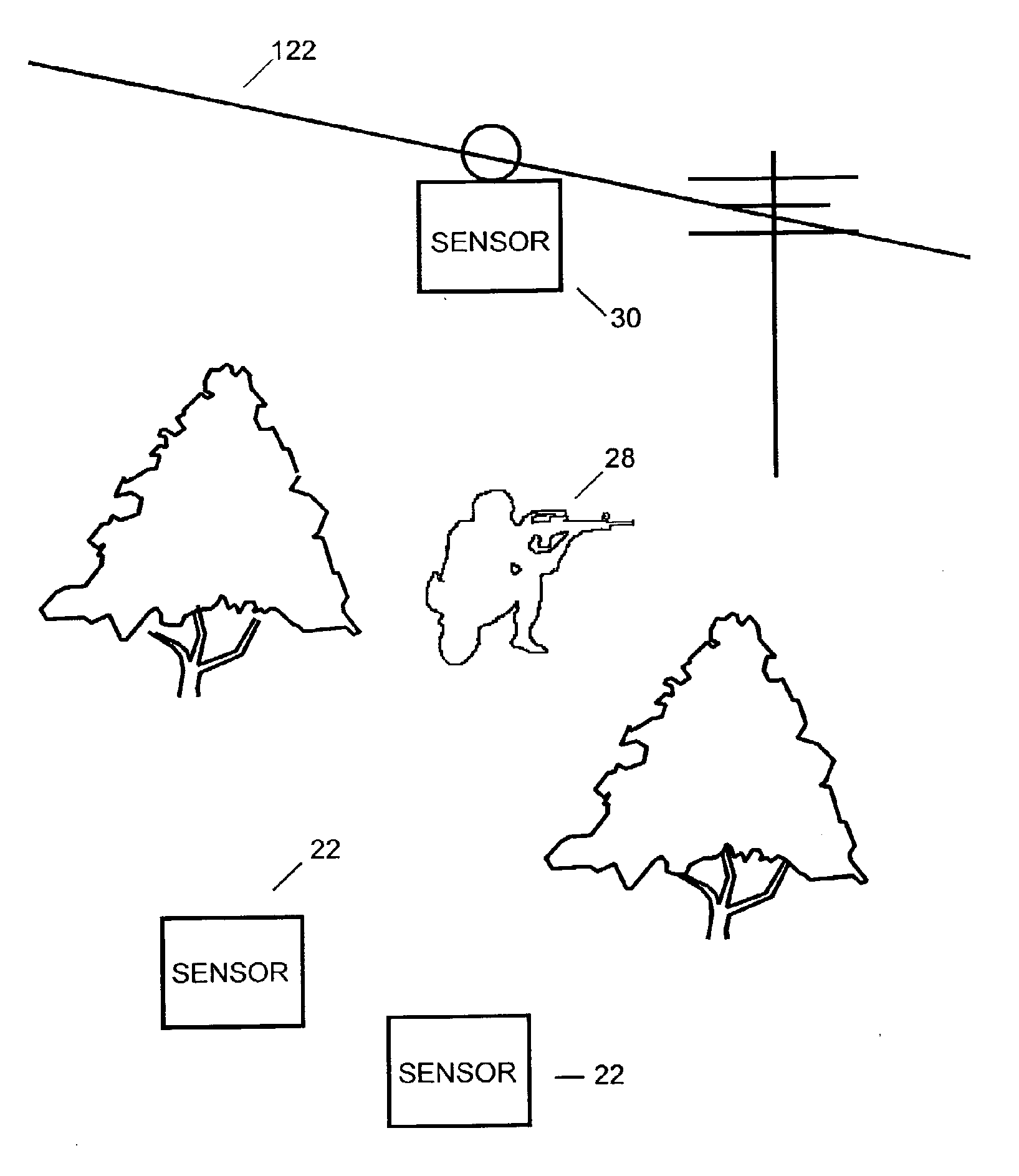
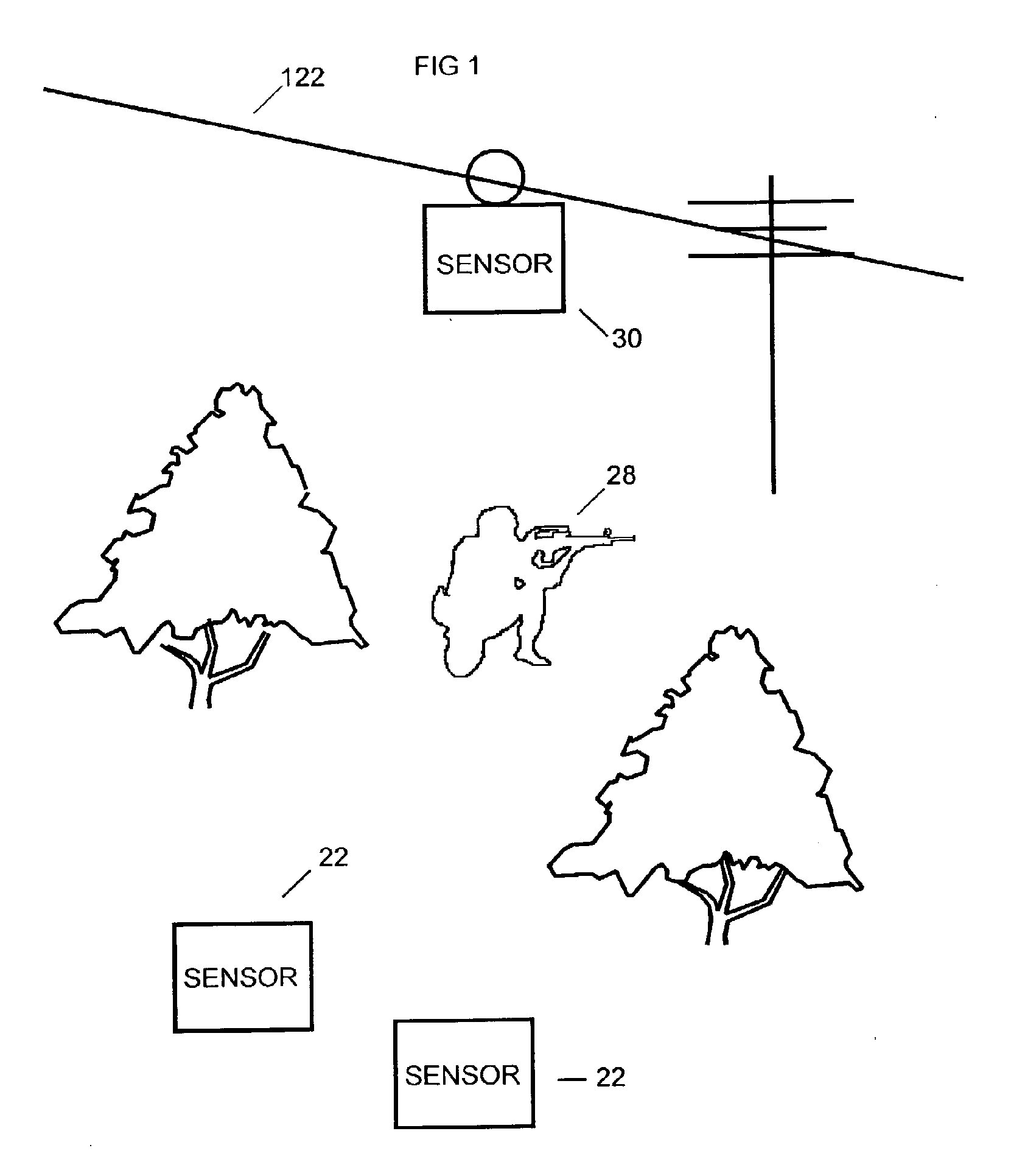
[0040]Referring now to the drawings, wherein like reference numerals indicate the same parts throughout the several views, a network of inventive sensors 22 and 30 are shown in their general environment in FIG. 1. In a preferred embodiment, a plurality of sensors 22 and 30 are dispersed over an area, typically at fairly regular intervals. Preferably, each sensor 22 is placed such that it has a relatively unobstructed acoustic view around its immediate area. By way of example and not limitation, suitable sites include: suspended from a...


PUM


Abstract

A system and method for detecting, identifying, and fixing the location of the source of an acoustic event. The inventive system includes: a plurality of sensors dispersed at somewhat regular intervals throughout a monitored area; a communication network adapted to deliver information from the sensors to a host processor; and a process within the host processor for determining, from the absolute times of arrival of an event at two or more sensors, a position of the source of the event. Acoustic events are detected and analyzed at each sensor so that the sensor transmits over the network: an identifier for the sensor; an identifier for the type of event; and a precise absolute time of arrival of the event at the sensor. In a preferred embodiment, the system also identifies the type of weapon firing a gunshot.

Description

CROSS REFERENCE TO RELATED APPLICATIONS[0001]This is a continuation of application Ser. No. 10 / 905,788, filed Jan. 20, 2005, published as publication No. 2005 / 0237186A1, which claims priority to Provisional Application No. 60 / 481,922, filed on Jan. 20, 2004, and is a continuation-in-part of application Ser. No. 10 / 248,511, filed Jan. 24, 2003, now U.S. Pat. No. 6,847,587, all of which are incorporated herein by reference in entirety.BACKGROUND[0002]1. Field[0003]The present invention relates to a system and method for identifying and locating an acoustic event. More particularly, but not by way of limitation, the present invention relates to a system for identifying an explosive event, such as a gunshot, at a remote location, reporting the event including a precise time of arrival to a host system, and calculating a location of the source of the event in the host system.[0004]2. Description of Related Art[0005]Generally speaking, there is a long felt need for a system and method to ...

Claims


Application Information

Patent Timeline
Patent Type & Authority Applications(United States)
IPC IPC(8): G01S3/00F41H13/00G01S5/18G08B1/08
CPCF41H11/00F41H13/00G01S5/0036G01S5/18H02J3/40G01S5/30G01S7/539G01S19/18G01V1/001G01S5/22
Inventor FISHER, KEN S.BAXTER, KEVIN
Owner SHOTSPOTTER
Why Eureka
Try Eureka