Transmission Device

a technology of transmission device and data transmission, which is applied in the field of transmission device, can solve problems such as packet collision, video/audio data being transmitted without meeting the desirable transmission quality,

Inactive Publication Date: 2008-09-11
SHARP KK
View PDF11 Cites 51 Cited by
  • Summary
  • Abstract
  • Description
  • Claims
  • Application Information

AI Technical Summary

Benefits of technology

[0044]According to an aspect of the present invention, a bandwidth can be automatically reserved for data transmission even when the transmission condition is not specified by the application since the determination unit organizes a set of packets having the same packet header as a packet group according to the classified result by the classification unit, and determines whether the packet group is to be transmitted with the bandwidth guaranteed according to the bit rate of the packet group.
[0045]Further, since the packet determination unit determines that the packet group is a packet group to be transmitted with the bandwidth guaranteed when the parameter calculated by the calculation unit is at most the preset value, determination of whether to transmit with a bandwidth guaranteed can be readily made.
[0046]Further, since the calculation unit increases the number of data to be the subject of calculation when the calculated parameter is greater than a preset value and recalculates the parameter, determination of whether to transmit with the bandwidth guaranteed can be carried out more strictly.
[0047]Further, since the calculation unit repeats the calculation of the parameter while sequentially increasing the number of data to be the subject until the para

Problems solved by technology

When two or more terminals take the same random backoff, packet collision may occur.
Since transmission is conduct

Method used


Image

  • Transmission Device
  • Transmission Device
  • Transmission Device

Examples


first embodiment

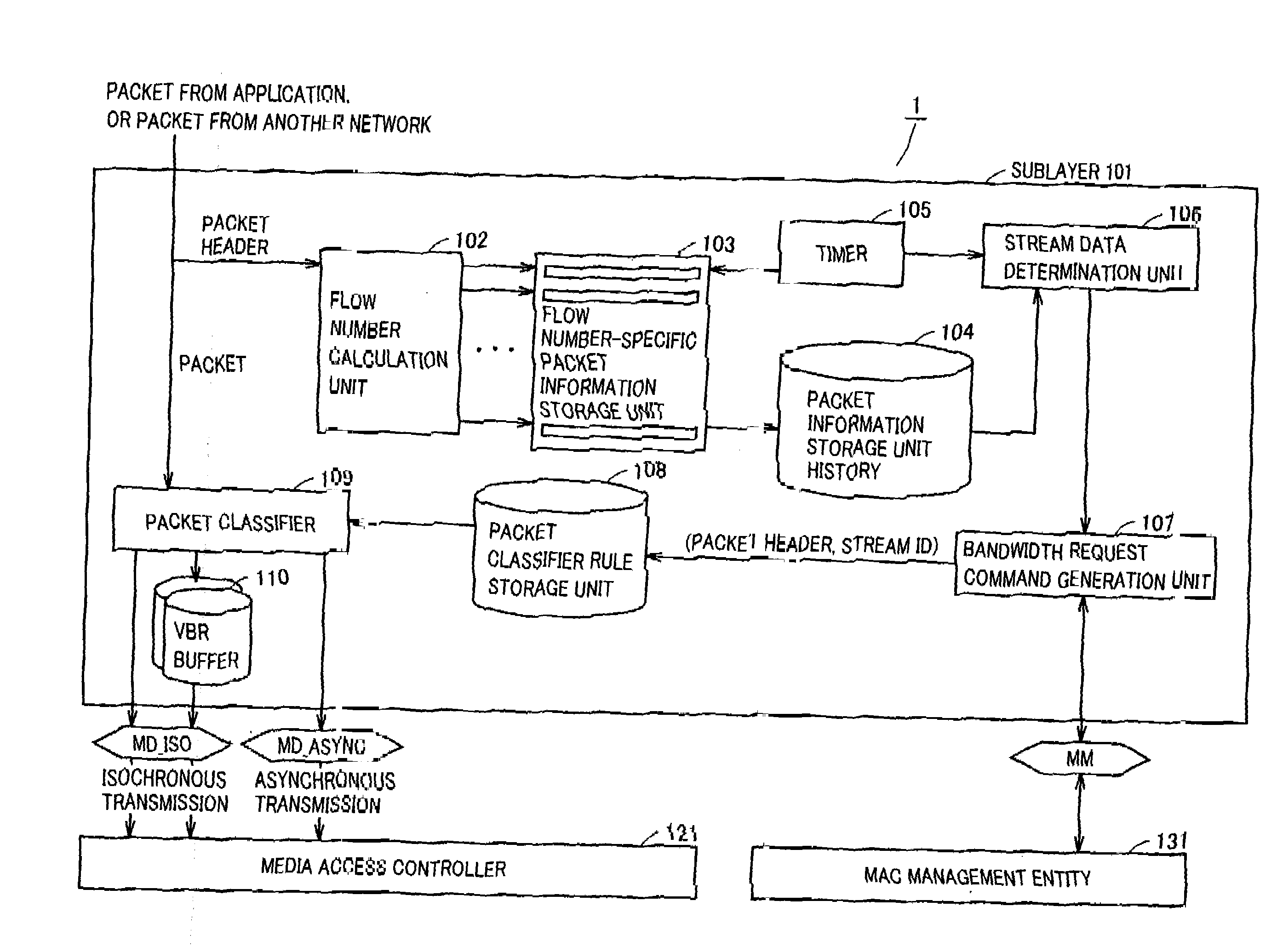
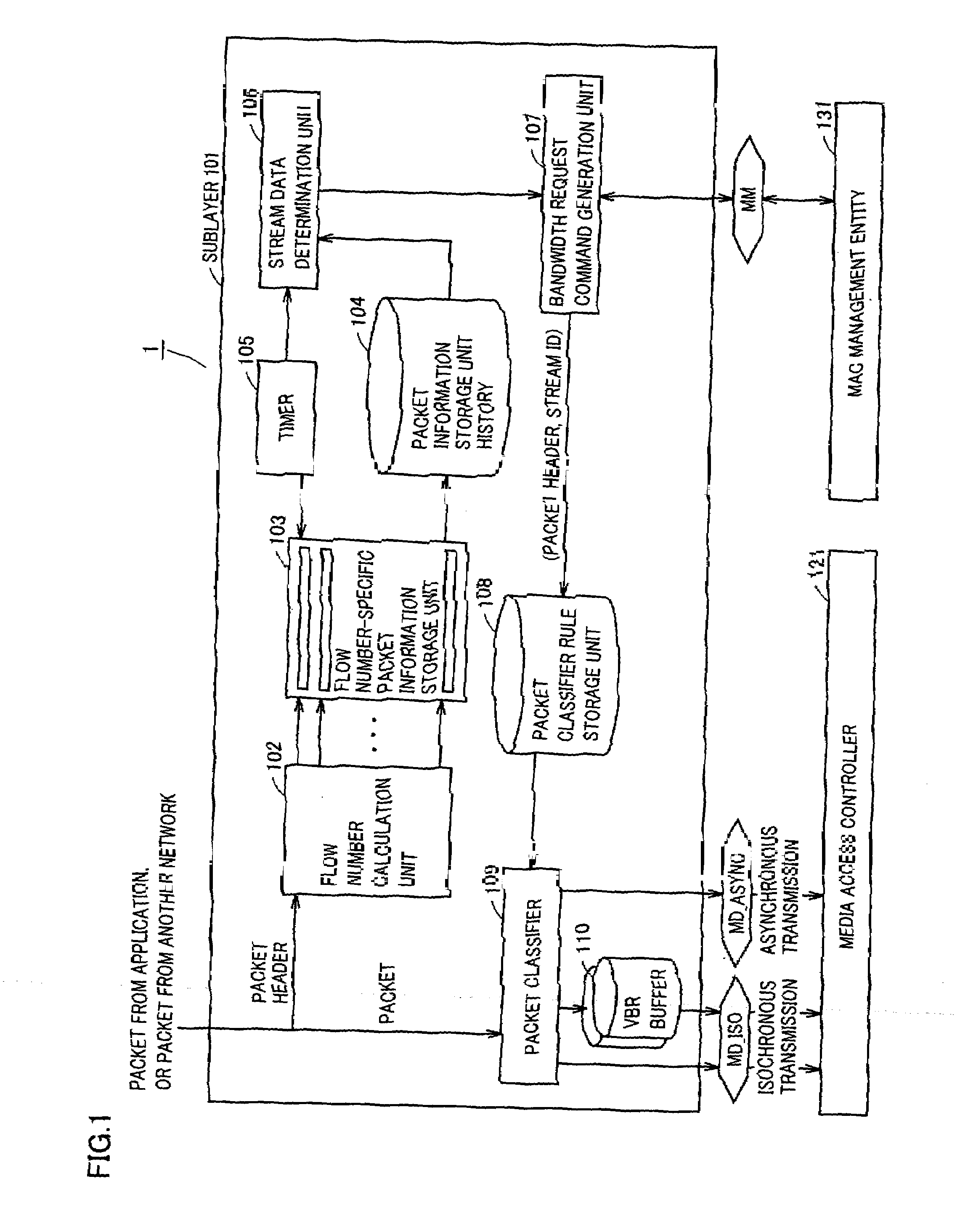
[0077]FIG. 1 is a block diagram representing a schematic configuration of a transmission device according to a first embodiment of the present invention. This transmission device 1 includes a sublayer 101 receiving a packet from an application or a packet from a different network to effect overall control of transmission device 1, a media access controller 121 for data transmission and reception via a medium such as radio, and a MAC management entity 131.

[0078]Media access controller 121 effects control related to data processing such as beacon transmission and reception, data transmission and reception while looking for the medium empty status, polling response, ACK generation, retransmission control, and the like.

[0079]MAC management entity 131 effects control relating to MAC management such as issuing a bandwidth request command to the bandwidth control device, processing a response from the bandwidth control device, administration of the medium unique ID, and the like.

[0080]Medi...

second embodiment

[0138]Although the transmission device described in the first embodiment of the present invention is valid for an application with a fixed bit rate, there are cases where the device is not valid for applications with a variable bit rate. The transmission device according to the second embodiment of the present invention is applicable to an application with a variable bit rate.

[0139]The transmission device according to the second embodiment of the present invention differs from the transmission device of the first embodiment in that a buffer 110 for VBR is added and the function of stream data determination unit 106 differs. Therefore, details of similar configuration and function will not be repeated. The stream data determination unit in the present embodiment is designated as reference number 106′.

[0140]FIG. 16 is a diagram to describe the concept of absorbing bit rate variation by VBR buffer 110. As shown in FIG. 16, even when the bit rate of the packet from an application input ...


PUM


Abstract

A flow calculation unit classifies packets of data to be transmitted according to each packet header. A stream data determination unit organizes a set of packets having the same packet header as a packet group according to the classified result by the flow number calculation unit, and determines whether to transmit with a bandwidth guaranteed according to the bit rate of the packet group. A bandwidth request command generation unit requests a bandwidth control device to reserve a bandwidth for the packet group determined to be transmitted with a bandwidth guaranteed by the stream data determination unit. Therefore, a bandwidth can be automatically reserved to allow data transmission even when no transmission condition is specified by the application.

Description

TECHNICAL FIELD[0001]The present invention relates to the technique for transmitting data on a network with QoS (Quality of Service) ensured. Particularly, the present invention relates to a transmission device monitoring a packet flowing on a transmission path of a network that ensures QoS, and identifying the flow to be transmitted with a bandwidth guaranteed to effect a bandwidth request to a bandwidth control device.BACKGROUND ART[0002]Recently, an attempt to transmit streaming data that requires real-time characteristics simultaneously with another data on a network such as a wireless LAN (Local Area Network) has been made, and is now beginning to be realized.[0003]Since data has various properties, the transmission condition that must be satisfied during transmission will differ depending upon the data. For example, in the field of WWW (World Wide Web) and file transfer, it is required that there is no error although some transmission delay is allowed.[0004]Streaming data such...

Claims


Application Information

Patent Timeline
IPC IPC(8): H04L12/28H04L12/56H04L47/762H04W28/00H04W28/26
CPCH04L12/5695H04L47/10H04L47/14H04L47/15H04W28/26H04L47/2441H04L47/724H04L47/828H04L47/2416H04L47/70H04W28/02H04W8/04
Inventor YAMADA, YUSUKE
Owner SHARP KK
Why Eureka
Try Eureka