Tape drive

a technology of tape drive and drive mechanism, which is applied in the direction of electric controllers, instruments, printing, etc., can solve the problems of many known drive mechanisms having difficulty delivering acceptable performance with a high degree of reliability, and the overall performance of the printer has, as a result, been compromised, and achieves simple overall mechanical assembly, high acceleration and deceleration rates, and low cost

Inactive Publication Date: 2008-09-11
ZIPHER
View PDF103 Cites 12 Cited by
  • Summary
  • Abstract
  • Description
  • Claims
  • Application Information

AI Technical Summary

Benefits of technology

[0035]A tape drive in accordance with certain embodiments of the present invention relies upon both the motors that drive the two tape spools to drive the tape during tape transport. Thus the two motors operate in push-pull mode. This makes it possible to achieve very high rates of acceleration and deceleration. Tension in the tape being transported is determined by control of the drive motors and therefore is not dependent upon any components that have to contact the tape between the take-up and supply spools. Thus a very simple overall mechanical assembly can be achieved. Given that both motors contribute to tape transport, relatively small and therefore inexpensive and compact motors can be used.

Problems solved by technology

Given that it is desirable to use large supply spools so as to minimise the number of times that a tape roll has to be replenished, this is a serious problem particularly in high-speed machines where rapid tape transport is essential.
For tape drives that use both a take-up motor and a supply spool motor, the variation in spool diameters can make it difficult to determine the correct drive signal to be supplied to each motor such that tape tension is maintained, and / or that tape is unwound or rewound at the correct rate.
Overall printer performance has, as a result, been compromised in some cases.
The requirements of high speed transfer printers in terms of tape acceleration, deceleration, speed and positional accuracy are such that many known drive mechanisms have difficulty delivering acceptable performance with a high degree of reliability.

Method used


Image

  • Tape drive
  • Tape drive
  • Tape drive

Examples


Embodiment Construction

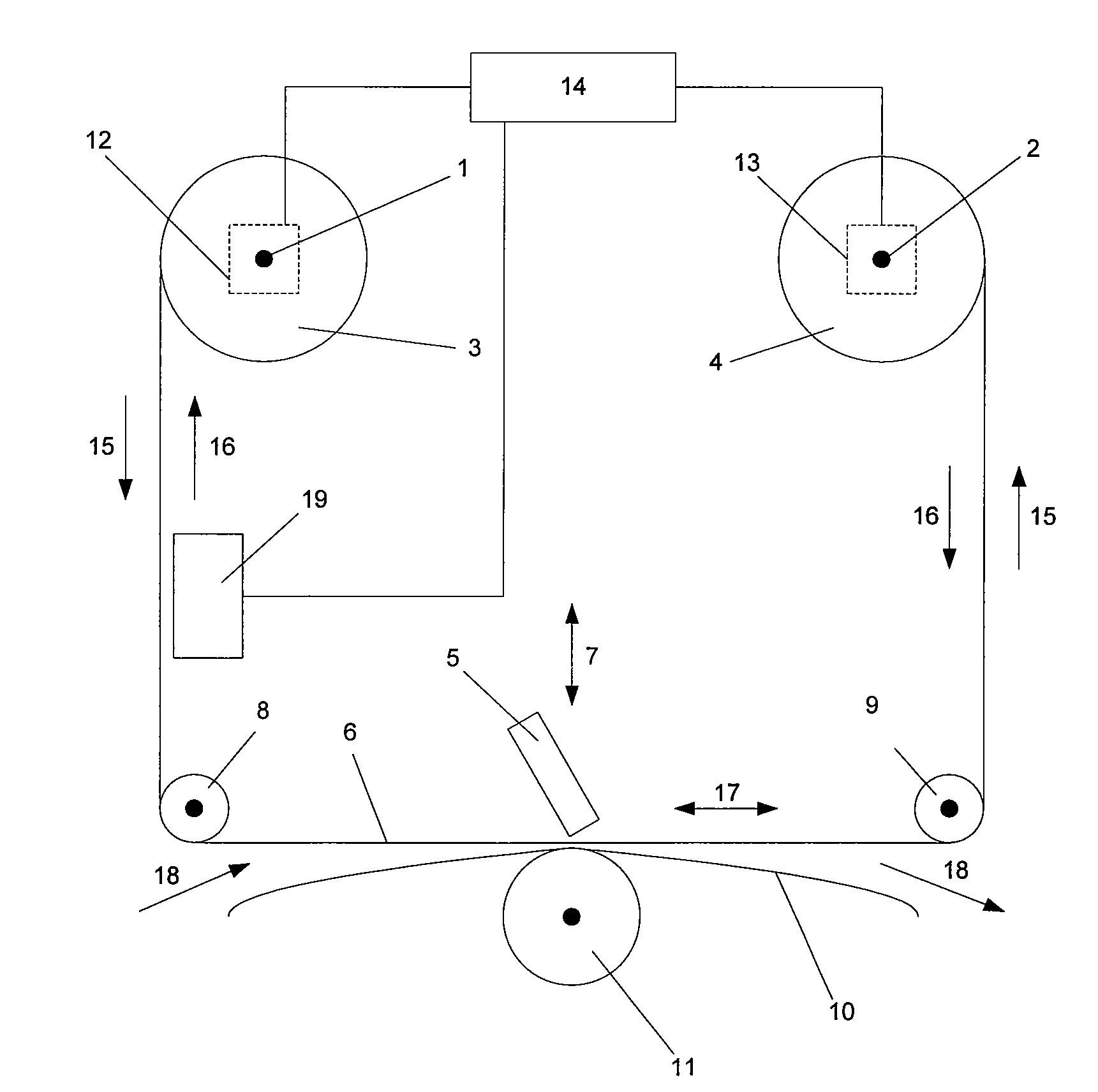
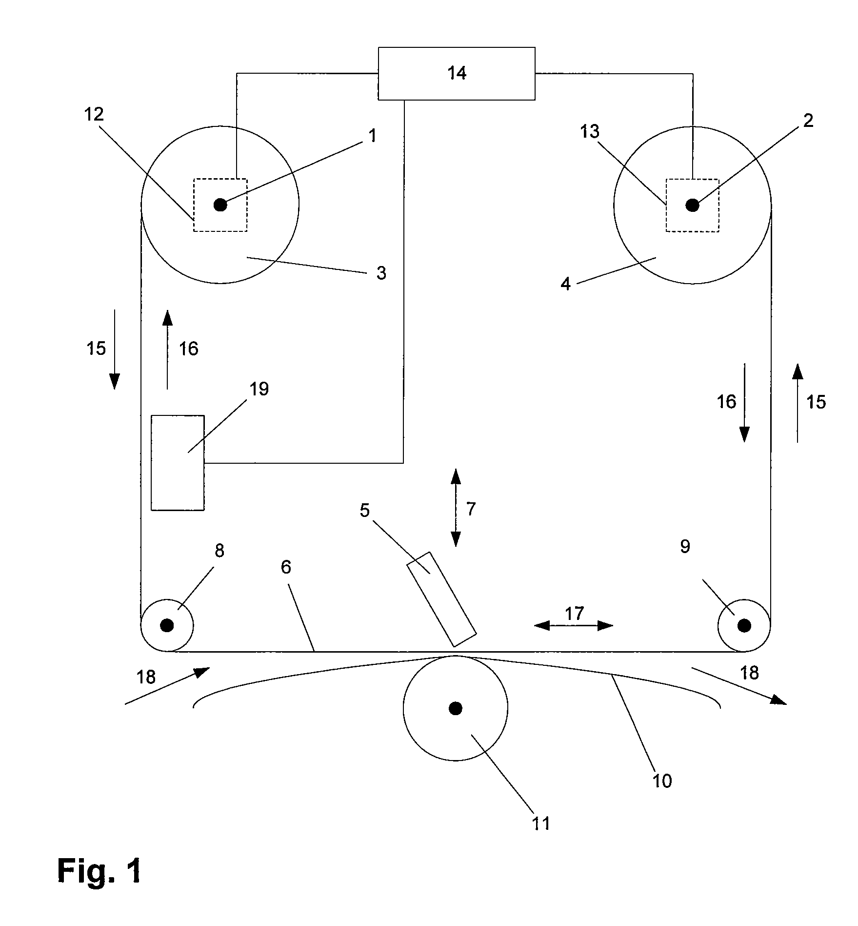
[0045]Referring to FIG. 1, this schematically illustrates a tape drive in accordance with the present invention suitable for use in a thermal transfer printer. First and second shafts 1, 2 support a supply spool 3 and a take-up spool 4 respectively. The supply spool 3 is initially wound with a roll of unused tape, and the take-up spool 4 initially does not carry any tape. As tape is used, used portions of the tape are transported from the supply spool 3 to the take-up spool 4. A displaceable printhead 5 is provided, displaceable relative to tape 6 in at least a first direction indicated by arrow 7. Tape 6 extends from the supply spool 3 around rollers 8, 9 to the take-up spool 4. The path followed by the tape 6 between the rollers 8 and 9 passes in front of the printhead 5. A substrate 10 upon which print is to be deposited is brought into contact with the tape 6 between rollers 8 and 9, the tape 6 being interposed between the printhead 5 and the substrate 10. The substrate 10 may b...


PUM


Abstract

A tape drive comprising first and second motors, two tape spool supports on which spools of tape may be mounted, each spool being drivable by a respective one of said motors, a sensor for sensing tape motion between the spools, and a controller. The controller is adapted to receive a first signal indicating demanded tape motion, provide a first control signal to at least one of the motors, the first control signal being based upon said demanded tape motion and being configured to cause tape to be transported between spools mounted on the spool supports, receive a second signal from said sensor indicating actual tape motion in response to said first control signal, and provide a second control signal to at least one of the motors, the second control signal being based upon said first and second signals.

Description

CROSS-REFERENCE TO RELATED APPLICATIONS[0001]This application claims priority to and is based on United Kingdom Application No. 0704369.8 filed Mar. 7, 2007, and incorporated herein by reference in its entirety.[0002]In addition, this application claims priority to and is based on U.S. Provisional Application No. 60 / 894,514 filed Mar. 13, 2007, and incorporated herein by reference in its entirety.BACKGROUND OF THE INVENTION[0003]The present invention relates to a tape drive. Such a tape drive may form part of printing apparatus. In particular, such a tape drive may be used in transfer printers, that is, printers which make use of carrier-supported inks.[0004]In transfer printers, a tape which is normally referred to as a printer tape and carries ink on one side is presented within a printer such that a printhead can contact the other side of the tape to cause the ink to be transferred from the tape on to a target substrate of, for example, paper or a flexible film. Such printers are...

Claims


Application Information

Patent Timeline
Patent Type & Authority Applications(United States)
IPC IPC(8): B41J33/02
CPCB41J33/34G05B1/01G05B11/01G05D13/02
Inventor MCNESTRY, MARTINBUXTON, KEITHYUNDT, GEORGE BORKEY
Owner ZIPHER
Why Eureka
Try Eureka