Tape drive and printing apparatus

a technology of printing apparatus and drive, which is applied in the direction of printing mechanisms, inking apparatus, instruments, etc., can solve the problems of overrun of supply spools, insufficient power of the ribbon transport system, and difficult maintenance of tolerances, and achieve the effect of convenient insertion of tapes

Inactive Publication Date: 2007-01-18
VIDEOJET TECH INC
View PDF99 Cites 7 Cited by
  • Summary
  • Abstract
  • Description
  • Claims
  • Application Information

AI Technical Summary

Benefits of technology

[0021] A tape drive in accordance with an exemplary embodiment relies upon both the motors which drive the two tape spools to drive the tape during tape transport. Thus the two motors operate in push-pull mode. This makes it possible to achieve very high rates of acceleration and deceleration. Tension in the tape being transported is determined by control of the drive motors and therefore is not dependent upon any components which have to contact the tape between the take-up and supply spools. Thus a very simple overall mechanical assembly can be achieved. Given that both motors contribute to tape transport, relatively small and therefore inexpensive and compact motors can be used.
[0031] One of the emitter and detector may be mounted on the transport mechanism, the other being fixed in position relative to the spools of tape, or alternatively both the emitter and detector may be mounted on the transport mechanism, the optical path between the emitter and detector being established by a mirror located at the side of the spools remote from the transport mechanism and arranged to reflect light from the emitter back to the detector. Spool diameters may be measured with the spools in a first position, the spools may then be rotated so that one spool rotates by for example 30°, the diameters may be measured again, and so on. This makes it possible to accurately assess spool eccentricity and outer circumference.
[0044] According to a second aspect of an exemplary embodiment, there is provided a transfer printer for transferring ink from a printer ribbon to a substrate which is transported along a predetermined path adjacent the printer, comprising a printer ribbon drive mechanism for transporting ribbon between first and second ribbon spools, a print head arranged to contact one side of the ribbon to press an opposite side of the ribbon into contact with a substrate on the predetermined path, a print head drive mechanism for transporting the print head along a track extending generally parallel to the predetermined substrate transport path and for displacing the print head into and out of contact with the ribbon, and a controller controlling the printer ribbon and print head drive mechanisms, the controller being selectively programmable either to cause the ribbon to be transported relative to the predetermined substrate transport path with the print head stationary and displaced into contact with the ribbon during printing, or to cause the print head to be transported relative to the ribbon and the predetermined substrate transport path and to be displaced into contact with the ribbon during printing.
[0050] This third aspect of an exemplary embodiment makes it possible to accurately determine spool sizes. In an apparatus such as a transfer printer with a displaceable print head the displaceable component can be readily mounted on the displaceable print head so as to require no additional electromechanical components over and above those necessary for the normal functioning of the apparatus.
[0060] Such arrangements are satisfactory in terms of performance but disadvantageous as valuable space is occupied by the lever mechanisms, thereby reducing the space available for taking large diameter spools of tape.
[0063] In an arrangement in accordance with the fifth aspect of an exemplary embodiment, when a cassette carrying a print ribbon is to be replaced, an electronic signal can be generated to cause transport of the print support assembly to a predetermined position (a “docked” position). This automatically retracts the print head away from the peel-off roller, enabling the easy insertion of a tape between the print head and peel-off roller.

Problems solved by technology

Given that it is desirable to use large supply spools so as to minimize the number of times that a ribbon roll has to be replenished, this is a serious problem particularly in high speed machines where rapid ribbon transport is essential.
Such tolerances are difficult to maintain as wear in the slipping clutch over time tends to change the resistive force exerted by the clutch.
If the clutch force is too great the ribbon transport system may have inadequate power to drive the ribbon throughout the range of spool diameters from a new supply roll to an empty supply roll.
Too little clutch force and slack in the ribbon could result in overrun of the supply spool.
Given these constraints, typical printer designs have compromised performance by way of limiting the rate of acceleration, the rate of deceleration, and the maximum speed capability of the ribbon transport system.
Overall printer performance has as a result been compromised.
The motors are not actively controlled to compensate for spool diameter variations.
With such an arrangement it is a relatively simple matter as described to provide feedback information concerning the magnitude of the ribbon spools so as to maintain a desired ribbon tension, but the overall system is complex.
The provision of such an idler roller and associated components adds to overall system complexities and cost.
None of the known arrangements is capable of coping well with the requirements of high speed industrial transfer printing systems.
The requirements in terms of ribbon acceleration, deceleration, speed and positional accuracy of high speed transfer printers is such that the known drive mechanisms have difficulty delivering acceptable performance with a high degree of reliability.
Similar constraints also apply in applications other than high speed printers.

Method used


Image

  • Tape drive and printing apparatus
  • Tape drive and printing apparatus
  • Tape drive and printing apparatus

Examples


Embodiment Construction

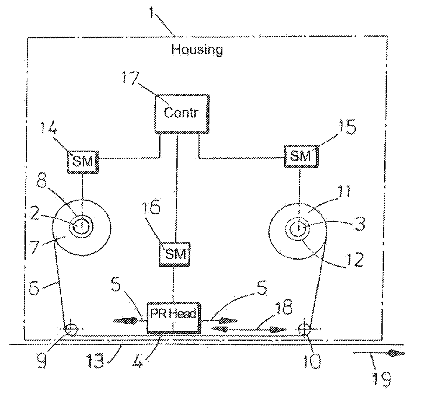
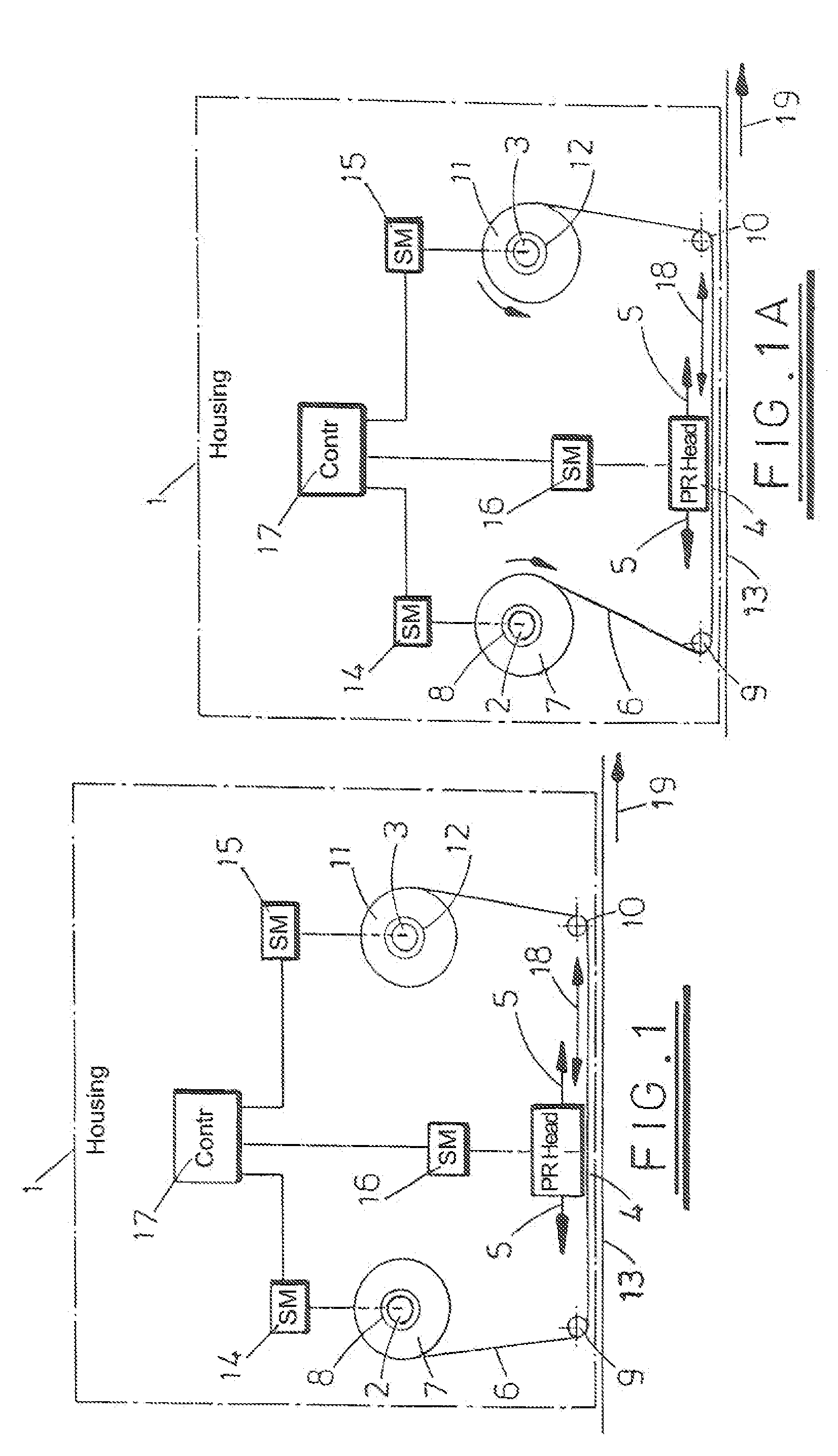
[0086] Referring to FIG. 1, the schematically illustrated printer in accordance with an exemplary embodiment has a housing represented by broken line 1 supporting a first shaft 2 and a second shaft 3. A displaceable print head 4 (PR Head) is also mounted on the housing, the print head being displaceable along a linear track as indicated by arrows 5. A printer ribbon 6 extends from a spool 7 received on a mandrel 8 which is driven by the shaft 2 around rollers 9 and 10 to a second spool 11 supported on a mandrel 12 which is driven by the shaft 3. The path followed by the ribbon 6 between the rollers 9 and 10 passes in front of the print head 4. A substrate 13 upon which print is to be deposited follows a parallel path to the ribbon 6 between rollers 9 and 10, the ribbon 6 being interposed between the print head 4 and the substrate 13.

[0087] The shaft 2 is driven by a stepper motor 14 (SM) and the shaft 3 is driven by a stepper motor 15 (SM). A further stepper motor 16 (SM) controls ...


PUM


Abstract

A tape drive for use in for example a transfer printing apparatus to drive a printer ribbon. The printer ribbon is mounted on two spools each of which is driven by a respective stepper motor. A controller controls the energization of the motor such that the ribbon is transported in at least one direction between spools mounted on the spool support. The controller is operative to energize both motors to drive the spools of ribbon in the direction of ribbon transport to achieve push-pull operations. Ribbon tension is monitored to enable accurate control of ribbon supply and ribbon take-up, the ribbon tension being monitored, for example, by monitoring power supply to the two stepper motors.

Description

RELATED APPLICATIONS [0001] This application is a continuation of U.S. application Ser. No. 10 / 380,182, filed Mar. 16, 2004, which is a US national phase of international application PCT / GB01 / 03965 which designated the U.S. and was filed Sep. 5, 2001, and claims benefit of GB 0022206.7 dated Sep. 11, 2000; GB 0028465.3 dated Nov. 22, 2000; GB 0100493.6 dated Jan. 9, 2001, and GB 0111044.4 dated May 2, 2001, the entire contents of all of these applications are hereby incorporated by reference.BACKGROUND [0002] 1. Technical Field [0003] This invention generally relates to tape drive and printing apparatus and to methods of operation for same and to apparatus and methods which may be used in transfer printers, that is printers which make use of carrier-supported inks. [0004] 2. Related Art [0005] In transfer printers, a tape which is normally referred to as a printer ribbon and carries ink on one side is presented within a printer such that a print head can contact the other side of th...

Claims


Application Information

Patent Timeline
Patent Type & Authority Applications(United States)
IPC IPC(8): B41J33/00B41J17/10B41J15/16B41J17/12B41J17/14B41J17/30B41J31/00B41J33/14B41J33/34B41J33/36B41J33/40B41J33/44B41J33/52B41J33/54B41J35/36B65H23/18
CPCB41J2/325B41J33/00B41J33/14B41J33/34B41J33/36B41J33/54G01B11/08B65H23/1806B65H2555/26B65H2701/372B65H2220/09B41J33/16
Inventor MCNESTRY, MARTINBUXTON, KEITHHART, PHILIP
Owner VIDEOJET TECH INC
Why Eureka
Try Eureka