High volume conveyor transport for clean environments

Inactive Publication Date: 2015-04-23
HORN GEORGE W
View PDF9 Cites 4 Cited by
  • Summary
  • Abstract
  • Description
  • Claims
  • Application Information

AI Technical Summary

Benefits of technology

The patent describes a conveyor system that reduces collisions between work piece carriers and increases throughput by dividing the conveyor into segments and allowing for local control of work piece carriers. The system also uses high friction coefficients to improve driving surface contact and avoid slippage on the belt. The use of elastic surface contacts and servo or stepper motor control allows for higher rates of acceleration and deceleration, improving throughput while avoiding collisions. The system also reduces particulation and drive motor torque requirements by using pliant rings that improve contact with the drive belt and minimize particulation. Overall, the system provides a collision-free flow of work carriers at high density and speed, increasing conveyor throughput.

Problems solved by technology

The limitations on stopping (or starting) distance in the prior art is a consequence of using rollers to drive the work piece carriers on a conveyor.
Thus, the physics of the limited contact surface between work piece carriers and the driving conveyor rollers required such moderate speeds.

Method used


Image

  • High volume conveyor transport for clean environments
  • High volume conveyor transport for clean environments
  • High volume conveyor transport for clean environments

Examples


Embodiment Construction

[0032]This application claims benefit over U.S. Provisional Application No. 61 / 894,079, filed Oct. 22, 2013, entitled: CONVEYOR SYSTEM PROVIDING REDUCED PARTICULATION.

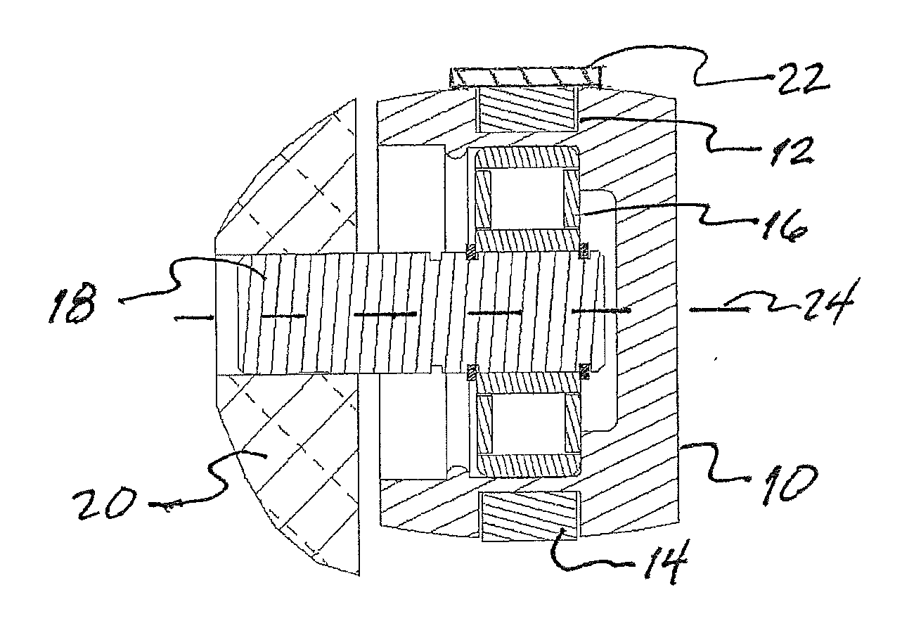
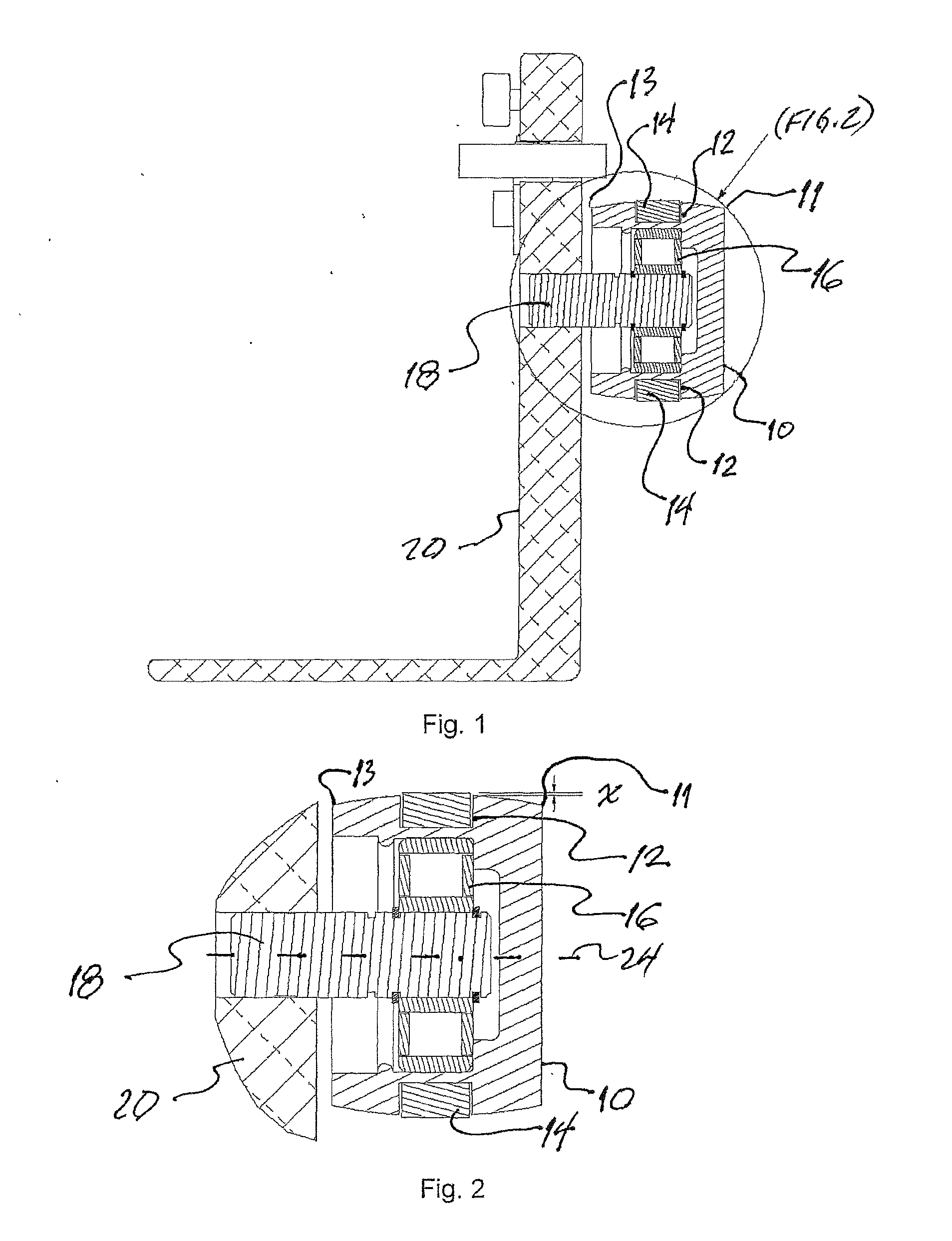
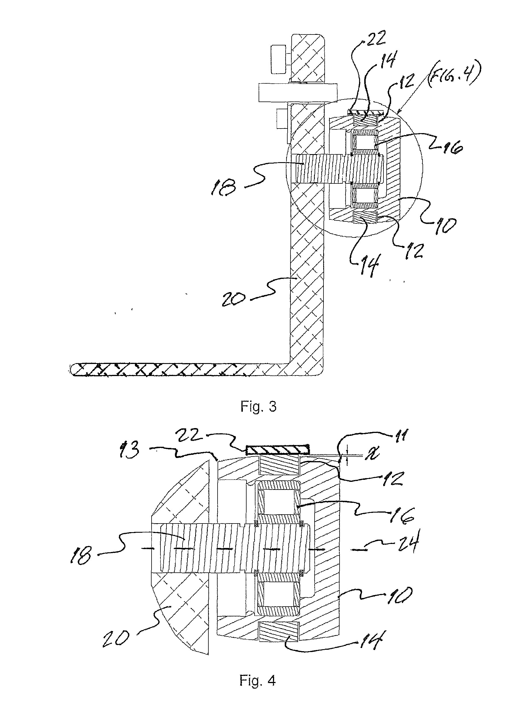
[0033]FIG. 1 illustrates an idler wheel hub 10 disposed in relation to a supporting rail frame 20. The wheel hub, also simply referred to herein as “the wheel,” may be formed of a hard, resilient material that is resistant to particulation, such as polyurethane. One preferred embodiment of the wheel 10 employs 75 Shore D cast electrostatic discharge (ESD) polyurethane rods that are machined to the desired shape and size after casting. Alternatively, a 67D polyester-type Thermoplastic Polyurethane (TPU) such as ESTANE (™ of Lubrizol Advanced Materials, Inc., Cleveland, Ohio) 58137 TPU. The wheel, in the illustrated embodiment, is substantially cylindrical, though, as can be more clearly seen in FIG. 2, has an outer periphery that is inclined with respect to an axis of symmetry 24 centered within the respective axle 18. ...


PUM


Abstract

A segmented, belt-driven conveyor system for use in clean environments. High speed, high density, collision free throughput of work piece carriers is enabled through belt-driven conveyor segments each having co-rotating drive wheels. The drive wheels have a cylindrical profile. Predefined acceleration / deceleration profiles may be employed by a motor controller to affect optimal changes in work piece carrier speed across the respective drive segment. A peripheral groove is formed in idler wheels within a drive segment. A soft, pliant ring of material is disposed in the groove. The ring protrudes slightly beyond the crown of each wheel. The drive belt then remains in contact with the ring when unloaded and the wheel peripheral surface itself when loaded through compression of the pliant ring. By reducing intermittent contact between the belt and the wheels, particulation is reduced.

Description

STATEMENT REGARDING FEDERALLY SPONSORED RESEARCH OR DEVELOPMENT[0001]N / ABACKGROUND OF THE INVENTION[0002]Many manufacturing factory environments consist of spatially distributed processing tools, as opposed to sequential tools located along a linearly arranged assembly line. This is especially true for manufacturing environments where work in process, or a “work entity,” re-enters a tool after being processed by another tool or tools. Re-entry into the same tool avoids tool duplication, which is particularly important in environments where the capital cost of the tools is high.[0003]A semiconductor manufacturing environment is an example of an environment where, due to high tool cost, a work entity enters a given tool, or type of tool, multiple times. Processing tools in a semiconductor manufacturing environment are typically spatially distributed in the factory according to function. Thus, the work flow resembles a chaotic movement of the work entity. With multiple work entities be...

Claims


Application Information

Patent Timeline
IPC IPC(8): B65G39/02B65G15/60B65G23/04B65G15/28
CPCB65G39/02B65G23/04B65G15/60B65G15/28B65G15/12B65G39/06B65G23/10
Inventor HORN, GEORGE W.
Owner HORN GEORGE W
Why Eureka
Try Eureka