
Disk protecting plate

Inactive Publication Date: 2008-09-11
CMC MAGNETICS CORPORATION
View PDF8 Cites 3 Cited by
  • Summary
  • Abstract
  • Description
  • Claims
  • Application Information

AI Technical Summary

Benefits of technology

[0008]A primary object of the present invention is to provide a disk protecting plate that has radially outward extended and inclined reinforcing ribs to enable reduced material but enhanced overall structural strength of the disk protecting plate.
[0009]Another object of the present invention is to provide a disk protecting plate that has radially outward extended and inclined reinforcing ribs to enable a reinforced but not too thick circumferential periphery to avoid damage of protected disks caused by compression or impact against the disk protecting plate.
[0011]The disk protecting plate with the radially outward inclined reinforcing ribs may be made with reduced material to obtain an enhanced overall structural strength without forming an excessively thick circumferential periphery, and a plurality of disks concentrically stacked and packaged between two pieces of the disk protecting plates could therefore be effectively protected against damage caused by compression or impact against the disk protecting plate.

Problems solved by technology

On the other hand, with the popularity of CD-related products and the gradually saturated CD market, and the fact that many local CD-related firms are restricted by foreign patents and have to pay extremely high royalty for producing patented CDs.
That is, it is a currently very important issue in the business field to develop ways for simplifying manufacturing process to upgrade product quality while effectively lowering the manufacturing and packaging costs.
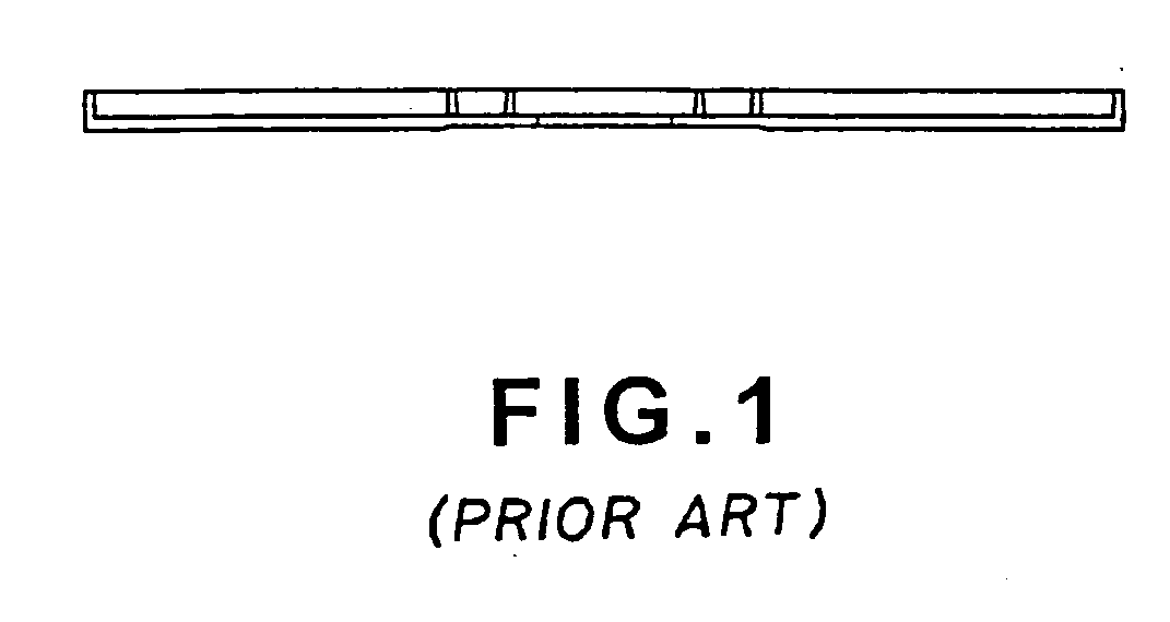
Since the above improved back-up plate is only strengthened along the circumferential periphery by the narrow peripheral wall thereof, the narrow peripheral wall of the back-up plate tends to break, crack, and / or collapse when the package of the stacked CDs is subjected to impact during transporting thereof.
Even if the packaged CDs are not damaged by such impact, the broken peripheral wall of the back-up plate visible from outside the package would adversely affect an overall appearance of the package to even result in rejection of the packaged CDs.

Method used


Image

  • Disk protecting plate
  • Disk protecting plate
  • Disk protecting plate

Examples


Embodiment Construction

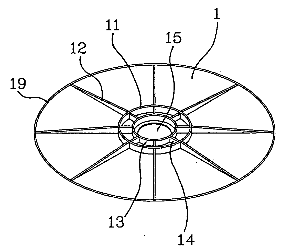
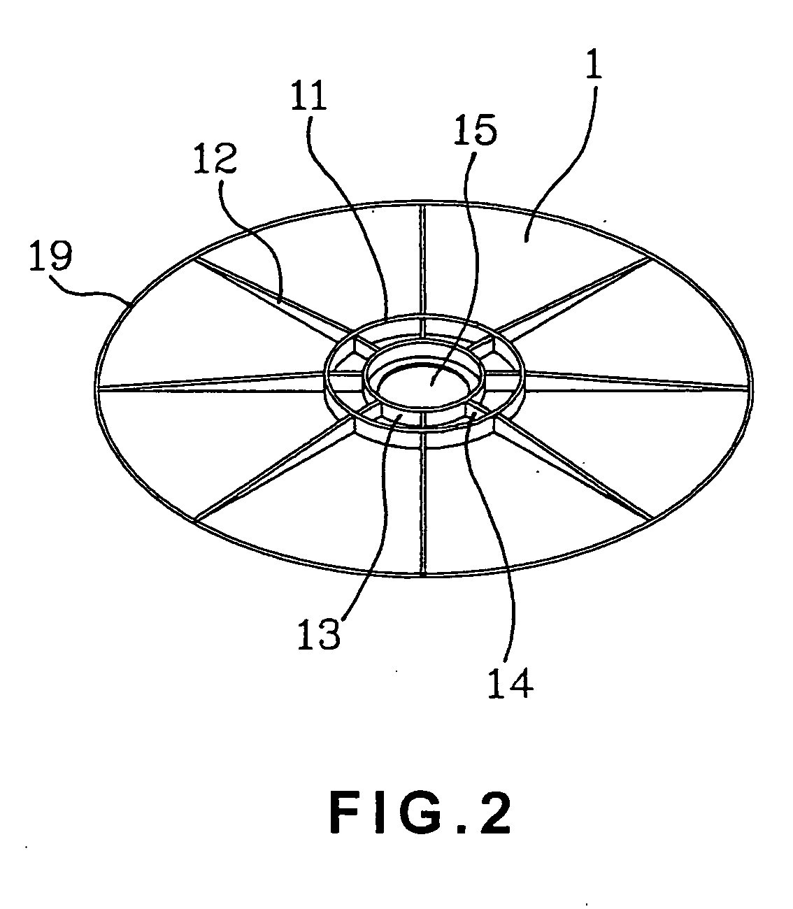
[0018]Please refer to FIGS. 2 and 3 that are top perspective and plan views, respectively, of a disk protecting plate according to the present invention, and to FIG. 4 that is a sectioned side view of the disk protecting plate.

[0019]As shown, the disk protecting plate of the present invention includes a disk-shaped plate body 1 having a central through hole 15. The plate body 1 is provided on a first side with a centered and diametrically larger outer annular wall 11, which is raised from the first side of the plate body 1 by a predetermined short distance. A plurality of reinforcing ribs 12 are radially outward extended from and equally spaced along the outer annular wall 11. Each of the reinforcing ribs 12 has a top gradually inclined toward an outer circumferential periphery of the plate body 1. A diametrically smaller inner annular wall 13 may be further formed on the first side of the plate body 1 to be concentric with the outer annular wall 11. A plurality of low-raised reinfo...


PUM


Abstract

A disk protecting plate includes a disk-shaped plate body having a central through hole. The plate body is provided on one side with a centered and low-raised annular wall, and a plurality of reinforcing ribs radially outward extended from the annular wall. Each of the reinforcing ribs has a top gradually inclined toward an outer circumferential periphery of the plate body. The disk protecting plate with the radially outward inclined reinforcing ribs may be made with reduced material to obtain a reinforced overall structural strength without forming an excessively thick outer periphery, and a plurality of disks concentrically stacked and packaged between two pieces of the disk protecting plates could therefore be effectively protected against damage caused by compression or impact against the disk protecting plate.

Description

FIELD OF THE INVENTION[0001]The present invention relates to a protecting plate used to protect concentrically stacked and packaged disks, and more particularly to a disk protecting plate that includes radially outward extended and inclined reinforcing ribs to enable reduced material but enhanced reinforcing effect and avoid damage of the protected disks caused by compression or impact against the disk protecting plate.BACKGROUND OF THE INVENTION[0002]In about 1980, the compact disk (CD) was first introduced to the market jointly by Philips and Sony. The CD is initially developed for the household appliance consumer market instead of computer storage. However, thanks to the easy portability, safety and durability, multimedia nature, big storage capacity, and low manufacturing cost thereof, the CD has been quickly applied in the storing of huge amount of computer data. With the rapidly increased market demands for CDs, many big-scale firms have successively engaged in the production ...

Claims


Application Information

Patent Timeline
IPC IPC(8): G11B7/24
CPCG11B33/0405
Inventor KE, WEN-BIN
Owner CMC MAGNETICS CORPORATION
Learn More