Sheet metal bending brake

a technology of bending brake and bending member, which is applied in the field of bending brake assembly, can solve the problems of affecting affecting the quality of bending parts, so as to facilitate relative movement, improve the precision of bending a sheet metal material, and reduce the amount of effort to elevate a bending member

Active Publication Date: 2008-09-18
WESTLAKE ROYAL BUILDING PROD INC
View PDF51 Cites 18 Cited by
  • Summary
  • Abstract
  • Description
  • Claims
  • Application Information

AI Technical Summary

Benefits of technology

[0007]The present invention provides such a bending brake assembly including a bearing strip being sandwiched between a male portion and a female portion for facilitating relative movement between the male portion and the female portion. The present invention further provides for an extension extending from a base and a finger extending from the male portion and defining a gap between the finger and the extension when in a pre-bending position with the finger maintaining the gap as the finger moves from the pre-bending position to a first operating position and the finger engaging the extension when in a second operating position for reducing an amount of effort to elevate a bending member and for improving a precision of bending a sheet metal material, In addition, the male portion contacts the sheet metal material in substantially a same relative position of contact during movement from the pre-bending position to the first and second operating positions which aids in minimizing marring of the sheet metal material. Additionally, the finger and the extension design eliminates having to machine some of the components as required in the prior art design as discussed above.
[0008]The bearing strip minimizes the erosion of the male portion due to the frictional force generated by the surface of the male portion sliding against the surface of the female portion during the process of bending a piece of sheet metal material.

Problems solved by technology

Also, a portion of the bending member abuts and moves along the sheet metal material as the bending member rotates to bend the sheet metal material, which may cause marring of the sheet metal material.
However, each of the projections and the opening of the bending member and each of the projections and the slot of the base are formed by machining which is expensive and time consuming to manufacture.
Constant and continuous usage of the bending brake assembly causes the male portion to erode due to the frictional force generated by the surface of the male portion sliding against the surface of the female portion during the process of bending a piece of sheet metal material.

Method used


Image

  • Sheet metal bending brake
  • Sheet metal bending brake
  • Sheet metal bending brake

Examples


Embodiment Construction

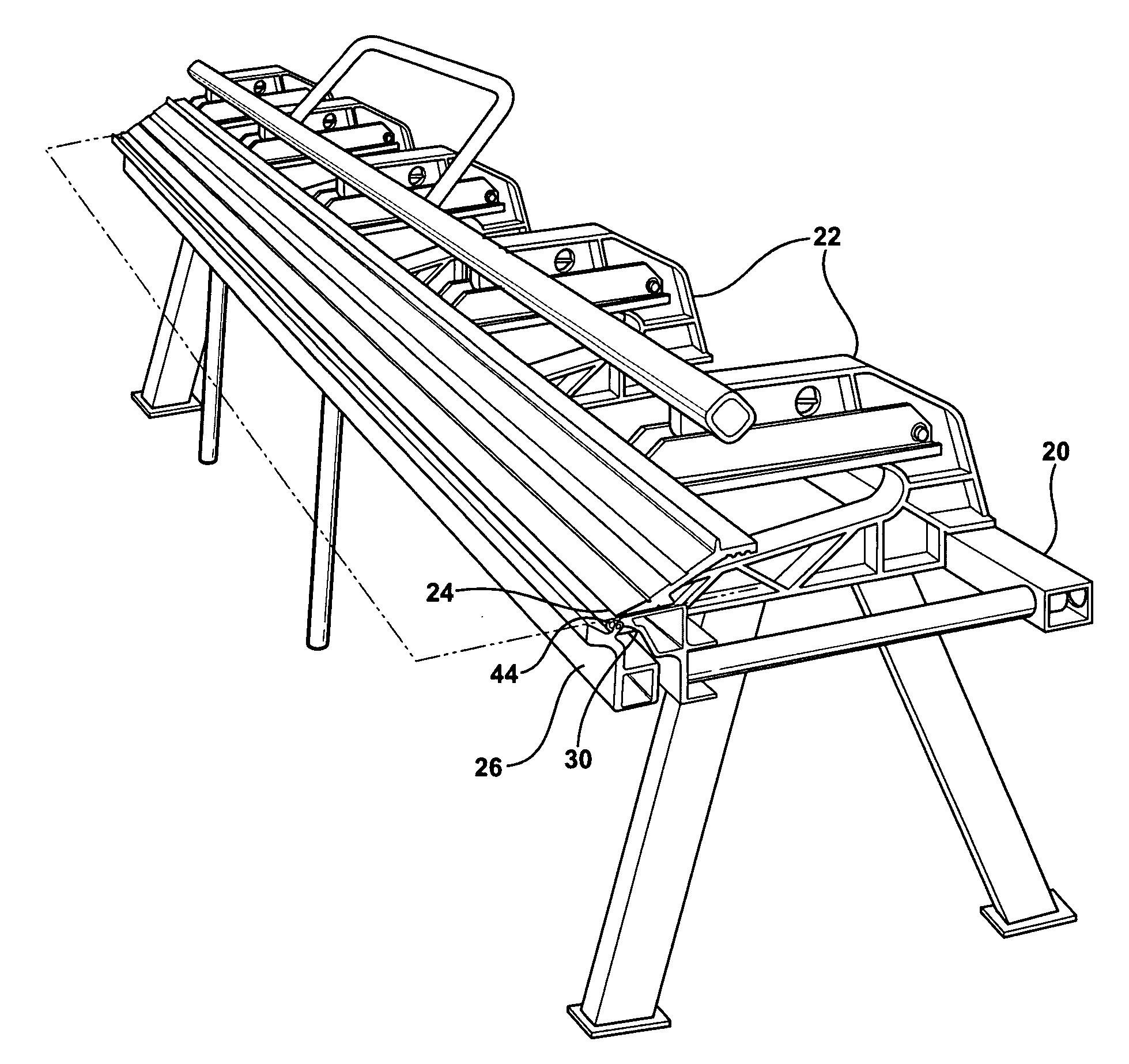
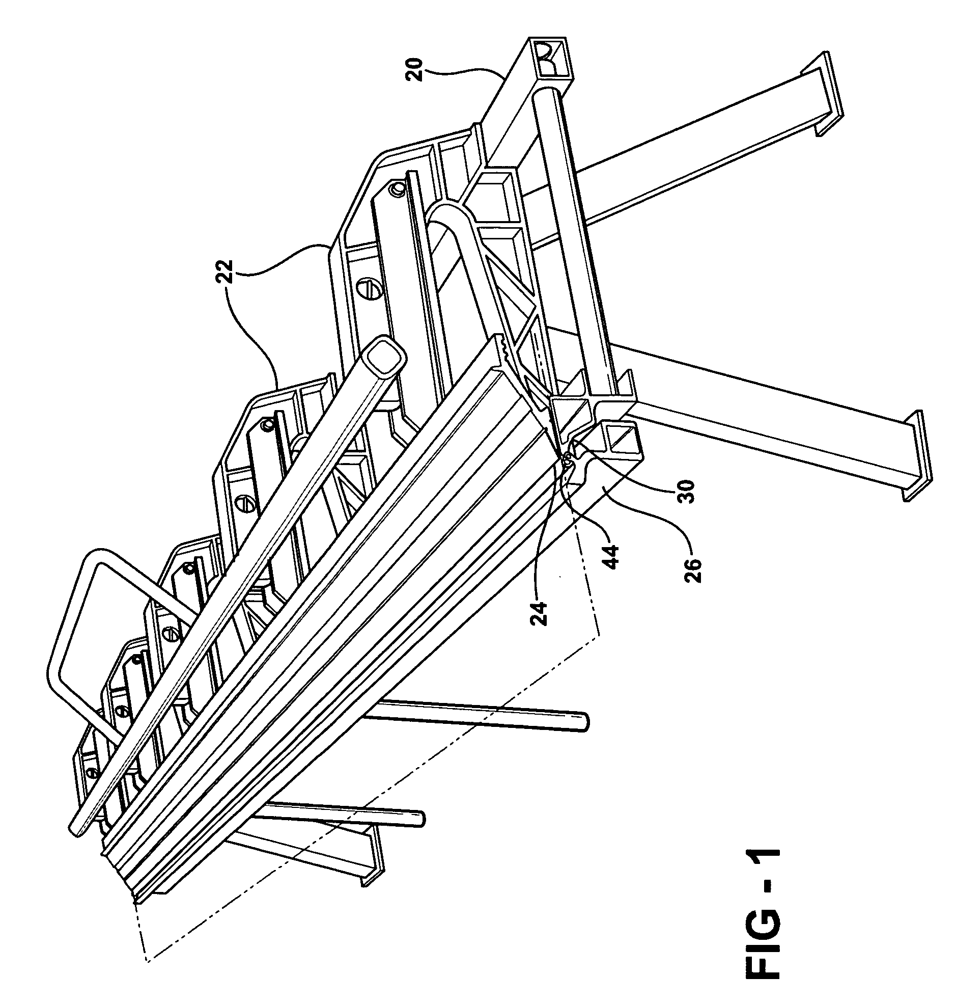
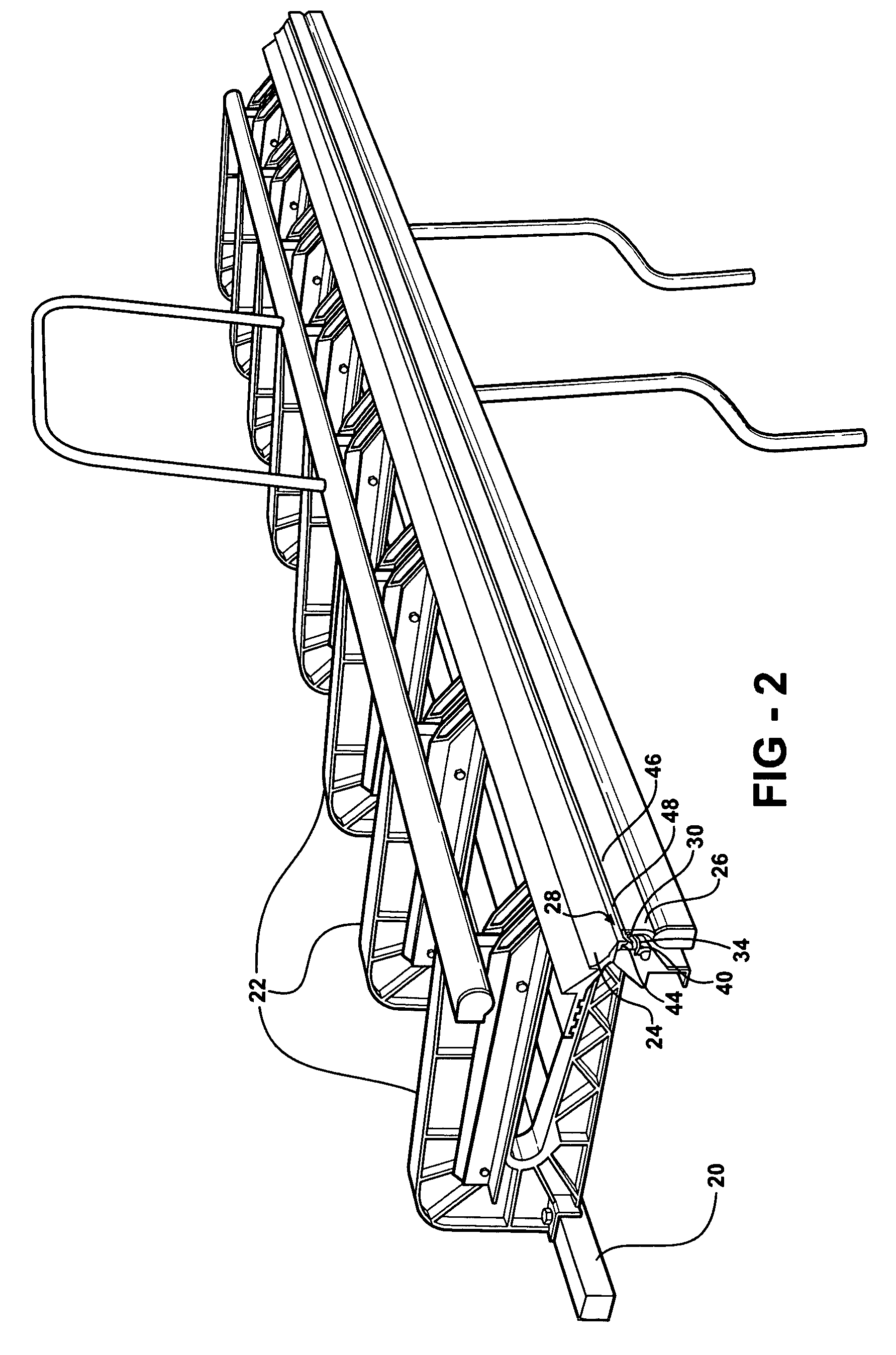
[0020]Referring to the Figures, wherein like numerals indicate corresponding parts throughout the several views, a bending brake assembly for manually bending pieces of sheet metal material is shown including a base (20). A plurality of generally c-shaped members (22) are supported by the base (20) and each c-shaped member (22) presents opposing clamping surfaces (24) for receiving a sheet metal material between the clamping surfaces (24). An extension (60) extends from the base (20) away from the clamping surfaces (24) to a distal end surface (62).

[0021]The bending brake assembly also includes a bending member (26). A socket connection (28) rotatably supports the bending member (26) on the base (20) for bending a piece of sheet metal material disposed between the clamping surfaces (24). The socket connection (28) includes a male portion (30) and a female portion (32) in sliding engagement with one another.

[0022]The bending brake assembly includes a bearing strip (34) being sandwich...


PUM

PropertyMeasurementUnit
bendingaaaaaaaaaa
sizeaaaaaaaaaa
relative movementaaaaaaaaaa

Abstract

A bending brake assembly for manually bending pieces of sheet metal material including a base supporting a plurality of c-shaped members presenting opposing clamping surfaces for receiving the sheet metal material. An extension extends away from the clamping surfaces with a socket connection rotatably supporting a bending member on the base for bending the sheet metal material disposed between the clamping surfaces. The socket connection includes a mate portion and a female portion in sliding engagement with one another as the bending member moves between a pre-bending position, a first operating position, and a second operating position. A finger extends from the male portion and defines a gap between the finger and the extension when in the pre-bending position with the finger maintaining the gap as the finger moves from the pre-bending position to the first operating position and the finger engaging the extension when in the second operating position.

Description

CROSS REFERENCE TO RELATED APPLICATION[0001]This application is a Continuation of U.S. Non-Provisional patent application Ser. No. 11 / 262,631 filed Oct. 31, 2005, which claims the benefit of U.S. Provisional Patent Application Ser. No. 60 / 623,468, filed Oct. 29, 2004, in which all contents are incorporated herein in their entirety.BACKGROUND OF THE INVENTION[0002]1. Field of the Invention[0003]The subject invention relates to a bending brake assembly for manually bending pieces of sheet metal material.[0004]2. Description of the Prior Art[0005]A bending brake assembly generally includes a base and a plurality of generally c-shaped members supported by the base and each presenting opposing clamping surfaces for receiving a sheet of metal material between the clamping surfaces. Furthermore, the assembly generally includes a bending member and a socket connection rotatably supporting the bending member on the base for bending a piece of sheet metal material disposed between the clampin...

Claims


Application Information

Patent Timeline
Patent Type & Authority Applications(United States)
IPC IPC(8): B21D5/04
CPCB21D5/04B21D5/042
Inventor ALLEN, CLYDE G.LAJEWSKI, TODD M.BREAK, DOUGLAS
Owner WESTLAKE ROYAL BUILDING PROD INC
Why Eureka
Try Eureka