Laser Machining Apparatus

Inactive Publication Date: 2008-09-18
HITACHI SEIKO LTD
View PDF11 Cites 13 Cited by
  • Summary
  • Abstract
  • Description
  • Claims
  • Application Information

AI Technical Summary

Benefits of technology

[0024]According to the present invention, mask patt

Problems solved by technology

The build-up method requires a more complicated manufacturing technique than the laminating method.
Various defects may be built in during these steps.
Progress of finer wiring patterns may increase the probability of occurrence of such defects.
Further, a resist exposure apparatus supporting finer wiring patterns is more expensive.
It is likely that improvement in performance of a package substrate leads to difficulty in reducing the manufacturing cost thereof.
One of problems of the laser patterning method is how to est

Method used


Image

  • Laser Machining Apparatus
  • Laser Machining Apparatus
  • Laser Machining Apparatus

Examples


Embodiment Construction

[0031]The present invention will be described below.

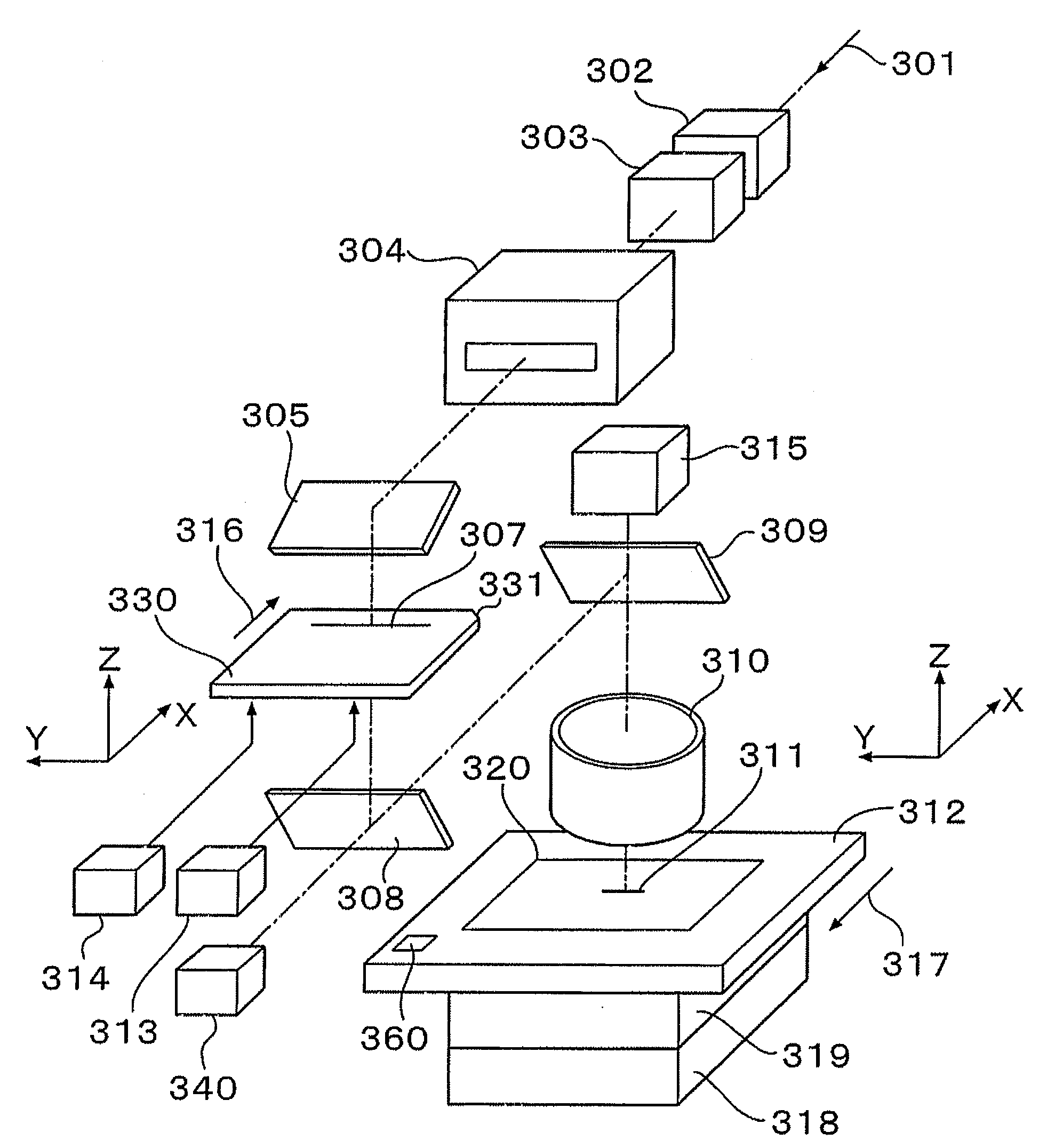
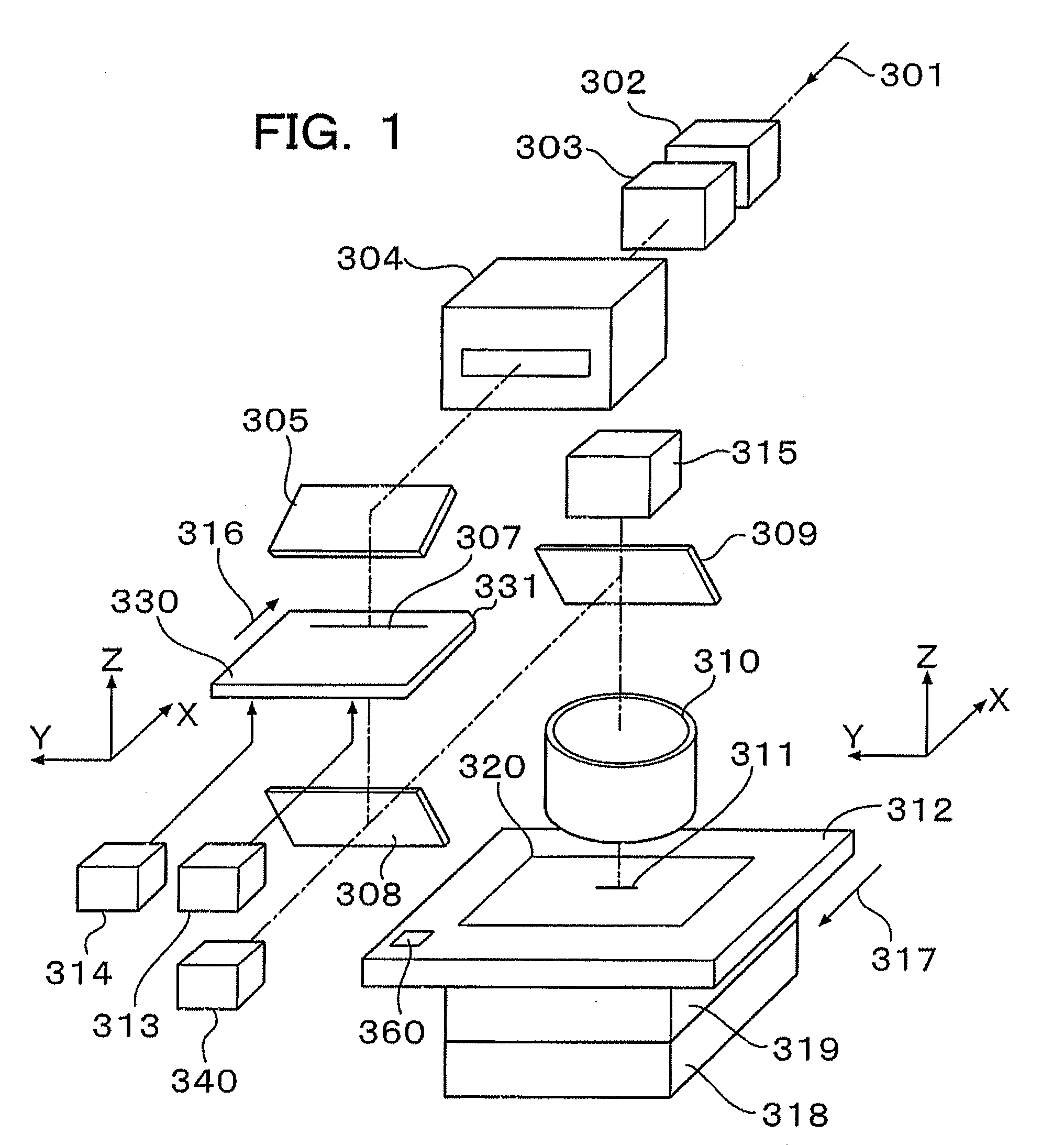
[0032]FIG. 1 illustrates a configuration of a laser machining apparatus according to the present invention.

[0033]A laser beam 301 emitted from a not-shown XeCl excimer laser oscillator (oscillation wavelength of 308 nm) is attenuated to a desired light intensity by an attenuator 302. The laser beam 301 is formed into a parallel beam by a collimator 303, and incident on a beam shaper 304. The beam shaper 304 changes the aspect ratio of the laser beam 301 incident thereon. The laser beam 301 emerges as a laser beam 307 having a substantially uniform (around ±3%) spatial intensity distribution. In this embodiment, the laser beam 307 measures 5 mm (X-direction) by 130 mm (Y-direction). The optical path of the laser beam 307 is deflected by a reflecting mirror 305, and the laser beam 307 is incident on a mask 330.

[0034]The mask 330 is fixedly positioned on a not-shown mask stage. The mask stage has moving mechanisms for X-, Y-, Z- and θ...


PUM

PropertyMeasurementUnit
Lengthaaaaaaaaaa

Abstract

A laser machining apparatus capable of accurately projecting mask patterns onto a work piece and superior in machining accuracy. An auto-focusing unit is provided. The auto-focusing unit includes a television camera for observing alignment marks formed on the surface of the work piece so as to be able to measure the focal length of a projection lens. A main-scanning direction expansion/contraction ratio Ex of the work piece to its design value and a sub-scanning direction expansion/contraction ratio Ey of the work piece to its design value are obtained. The imaging magnification M of the projection lens is corrected to compensate the expansion/contraction ratio Ex. The moving speed of a mask and/or the moving speed of the work piece are corrected in consideration of the imaging magnification M of the projection lens so as to compensate the expansion/contraction ratio Ey.

Description

FIELD OF THE INVENTION[0001]The present invention relates to a laser machining apparatus for irradiating a work piece with a laser beam having passed through a mask pattern, so as to machine a surface of the work piece.BACKGROUND OF THE INVENTION[0002]With higher performance and smaller size of electronic instruments such as personal computers, thin TV sets, cellular phones, etc., wiring patterns in printed circuit boards serving as constituents of these instruments have been made finer in structure and higher in density. This tendency is conspicuous in a printed circuit board used for mounting a large-scale semiconductor chip. Such a printed circuit board will be referred to as “package substrate” hereafter. In recent years, wiring patterns have been made fine to be about 10-20 micrometers (μm) in minimum line width. In order to support the trend toward higher density and higher speed in semiconductor integrated circuits, it is believed that wiring patterns are requested to have si...

Claims


Application Information

Patent Timeline
IPC IPC(8): B23K26/02B23K26/00
CPCB23K26/03B23K26/032B23K26/04B23K26/043B23K26/0738B23K26/0861B23K26/042B23K26/066B23K2101/40B23K2101/42
Inventor MARUYAMA, SHIGENOBUAOYAMA, HIROSHISHIGA, MASAYUKIOHMAE, GOICHI
Owner HITACHI SEIKO LTD
Why Eureka
Try Eureka