Dimmer switch assembly

a technology of dimmer switch and assembly, which is applied in the direction of lighting apparatus, instruments, light sources, etc., can solve the problems of circuits adding cost and complexity to switches, inductive loads, and devices to be triggered when, so as to prevent misfiring of switches

Active Publication Date: 2008-09-18
RICHTER EDWARD J
View PDF6 Cites 39 Cited by
  • Summary
  • Abstract
  • Description
  • Claims
  • Application Information

AI Technical Summary

Benefits of technology

[0013]A snubber circuit is connected across ...

Problems solved by technology

However, inductive loads are a concern when using a thyristor to control switching the power wave of from an AC power source.
With inductive loads, dV/dt may become too large, and the sudden rise in voltage can cause the device to be triggered when not desired.
However, these circuits add cost and complexity to the switch.
An...

Method used


Image

  • Dimmer switch assembly
  • Dimmer switch assembly
  • Dimmer switch assembly

Examples


Embodiment Construction

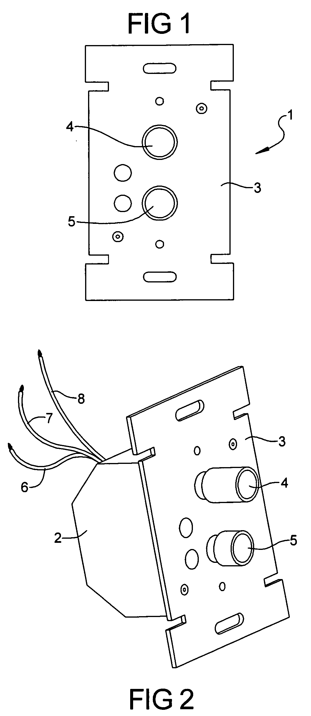
[0019]Referring now to FIG. 1, a front view of the dimmer switch 1 according to the principles of the present invention for controlling the illumination level of a lamp or light by controlling the delivery of alternating current electrical voltage from a source to the load reveals a strap supporting an on / off switch 4 and dimmer control switch 5. The on / off switch 4 enables a user to selectively conduct power to the load while the dimmer control switch 5 is coupled to a variable resistor, enabling a user to adjust the resistance of the variable resistor, or potentiometer, as it is referred to herein.

[0020]Referring now also to FIG. 2, a perspective view of the dimmer switch 1 of FIG. 1 reveals the strap 3 mounted on a housing 2 and connection wires 6,7,8 leading from the housing 2. The housing 2 contains an electrical circuit which is mounted on the strap 3, which also functions as a heat sink for the circuit.

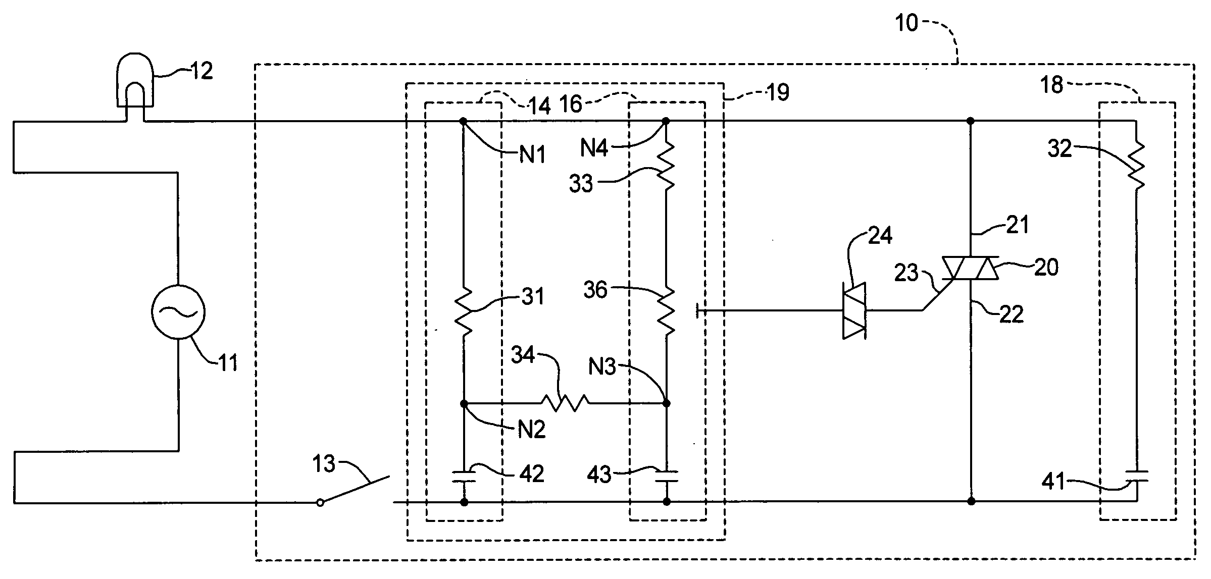
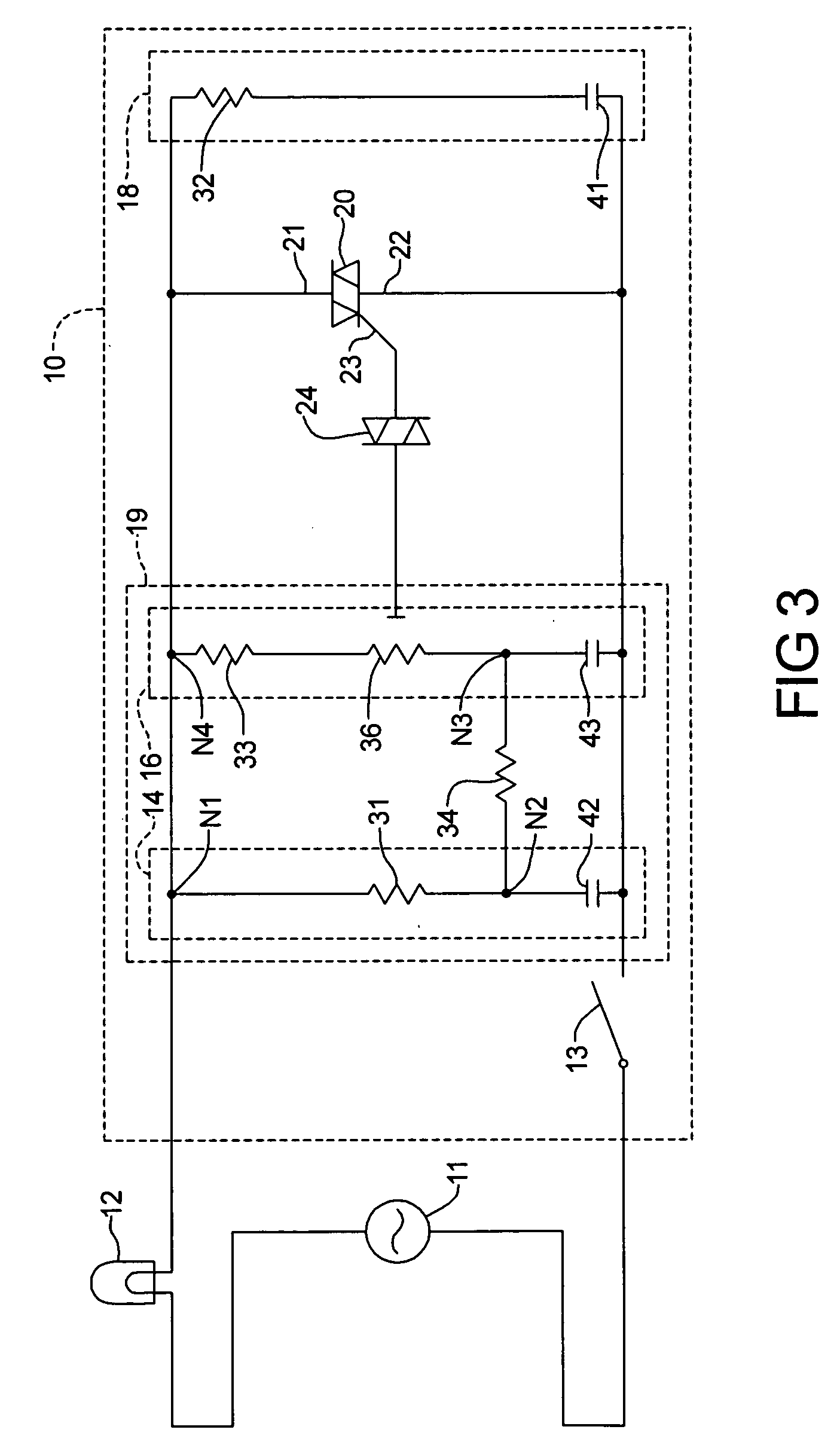
[0021]Referring now to FIG. 3, a schematic representation of the electrica...


PUM


Abstract

Disclosed herein is a dimmer switch having a broad range of control with a relatively simple circuit having a number of safety features. The circuit employs a triac and diac to selectively conduct an AC power wave. A variable phase shift network having an improved range of control governs the firing angle of the diac. The variable phase shift network includes a first and second series R-C circuits coupled by a bridge resistor.

Description

CROSS-REFERENCE TO RELATED APPLICATION[0001]This application is a completion application of co-pending U.S. Provisional Application No. 60 / 906,061 filed on Mar. 9, 2007, for “Dimmer Switch Assembly,” the entire disclosure of which is hereby incorporated by reference.BACKGROUND OF THE INVENTION[0002]1. Field of the Invention[0003]The present invention relates to a dimmer switch for controlling the delivery of electrical voltage from a source to load which is especially useful in dimming lamps. More specifically, the invention relates to a dimmer switch having a broader range of control with a relatively simple circuit having a number of safety features.[0004]2. Prior Art[0005]Modern control circuits for dimmer switches commonly use a thyristor, most commonly a triac, to chop the AC power wave from an AC voltage source to the load, such as an incandescent light. A gate controls current flow through the triac, which is signaled to conduct by current flow through the gate. The switch th...

Claims


Application Information

Patent Timeline
IPC IPC(8): H05B37/02
CPCH05B39/08
Inventor RICHTER, EDWARD J.
Owner RICHTER EDWARD J
Why Eureka
Try Eureka