Warning System

a technology of warning system and warning plate, which is applied in the direction of brake safety system, vehicle components, antineoplastic agents, etc., can solve the problems of serious personal injury and property damage, annoy the driver, and the vehicle may under its own weight start rolling away, so as to achieve simple and cost-effective

Inactive Publication Date: 2008-09-18
SCANIA CV AB
View PDF12 Cites 21 Cited by
  • Summary
  • Abstract
  • Description
  • Claims
  • Application Information

AI Technical Summary

Benefits of technology

[0007]The object of the present invention is to achieve a warning system capable of generating a warning so as to alert the driver of a vehicle that the parking brake is not properly engaged when he / she is about to leave the vehicle cabin while leaving the vehicle engine running and also capable of alleviating the above-indicated problem of undesired warning signals, and which may be implemented in a rather simple and cost-efficient manner.

Problems solved by technology

If the driver of a vehicle forgets to engage or fails to properly engage the parking brake of the vehicle prior to leaving it when parked on a slope, the vehicle may under its own weight start rolling away.
Such accidental situations may cause serious personal injuries and property damages, especially when it comes to heavy motor vehicles such as lorries, towing vehicles or buses.
However, the warning system should not generate warning signals undesirably, e.g. in situations where the driver, after having stopped the vehicle, intends to remain seated in the vehicle with the parking brake disengaged in order to reverse the vehicle or operate the vehicle in another manner.
Such undesired warning signals will annoy the driver and could, if frequently occurring, make the driver less attentive to the warning signal in a situation when he / she actually has omitted to engage the parking brake or even make the driver disable the entire warning system.
Thus, this known warning system suffers from the above-indicated drawback of undesired warning signals.
However, sensors for detecting whether or not the driver's seat is occupied are normally not included as standard components in motor vehicles, which will make it rather costly to implement this known warning system.
Furthermore, existing sensors of this type are in general not very reliable, which may result in annoying warning signals during driving or in the lack of warning signals when the driver leaves the vehicle without having engaged the parking brake.

Method used


Image

  • Warning System
  • Warning System
  • Warning System

Examples


Embodiment Construction

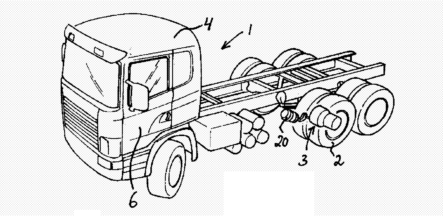
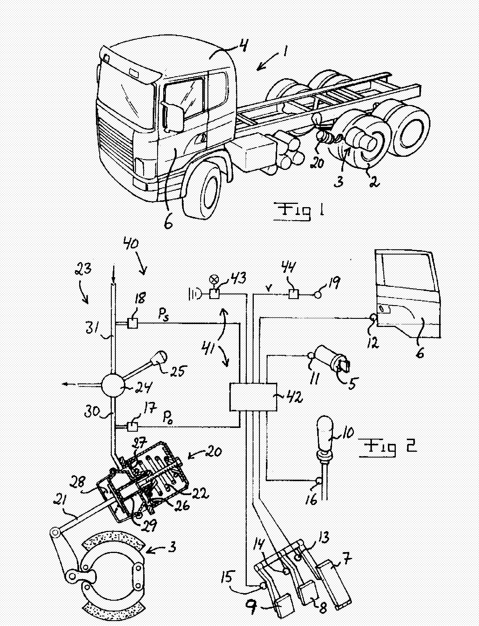
[0029]A motor vehicle 1 in the form of a towing vehicle is schematically illustrated in FIG. 1. This vehicle 1 is provided with a pneumatic parking brake circuit including a number of brake cylinders 20, one for each vehicle wheel 2 to be locked by the parking brake. Only the brake cylinder 20 of one of the vehicle wheels 2 is illustrated in FIG. 1. A reciprocable push rod 21 projecting from the brake cylinder 20 is operably connected to braking means 3 for holding the wheel 2 against rotation when the push rod 21 is axially displaced into an advanced position and releasing the wheel for rotation when the push rod 21 is axially displaced into a retracted position. The brake cylinder 20 is of conventional design and is illustrated in longitudinal section in FIG. 2. The push rod 21 is axially displaceable from the advanced position to the retracted position against the action of a compression spring 22. The parking brake is engaged by the action of the compression spring 22 and is rel...


PUM


Abstract

A warning system and a method for alerting a driver of a vehicle that the parking brake of the vehicle is not engaged by generating a warning when the following conditions are simultaneously fulfilled: the ignition of the vehicle is on, the driver access door of the vehicle cabin is open, no throttle lever, or clutch lever or brake lever of the vehicle is activated, the gear shift lever of the vehicle is in the neutral position, and the parking brake is not engaged, and not when—the pressure of a pneumatic circuit associated with the parking brake is below a threshold,—the vehicle speed exceeds a threshold.

Description

TECHNICAL FIELD [0001]The present invention relates to a warning system for a motor vehicle provided with a parking brake, wherein the system comprises warning means adapted to generate, under certain predetermined conditions, a warning so as to alert the driver that the parking brake is not engaged. The invention also relates to a method for alerting a driver of a vehicle that the parking brake of the vehicle is not engaged. Furthermore, the invention relates to a computer program comprising computer program code for implementing such a method, a computer program product comprising a data storage medium readable by an electronic control unit and having such a computer program stored thereon, and an electronic control unit.BACKGROUND ART [0002]If the driver of a vehicle forgets to engage or fails to properly engage the parking brake of the vehicle prior to leaving it when parked on a slope, the vehicle may under its own weight start rolling away. Such accidental situations may cause...

Claims


Application Information

Patent Timeline
Patent Type & Authority Applications(United States)
IPC IPC(8): B60Q1/00
CPCB60T17/22A61P35/00B60Q9/00
Inventor LUNDGREN, STENBERGQVIST, OLA
Owner SCANIA CV AB
Why Eureka
Try Eureka